Diagnostics (RS48)
This connector is labeled as "Diagnostics RS48," however Mercury's CDS G3 diagnostic tool always connects to the 10‑pin
SmartCraft connection. This connector is used instead for the connection of a depth transducer. The PCM communicates with
the transducer and then broadcasts the information onto the SmartCraft network for display at the helm. CDS G3 will also
display the depth data under the Vessel tab of the Live Data display for troubleshooting purposes.
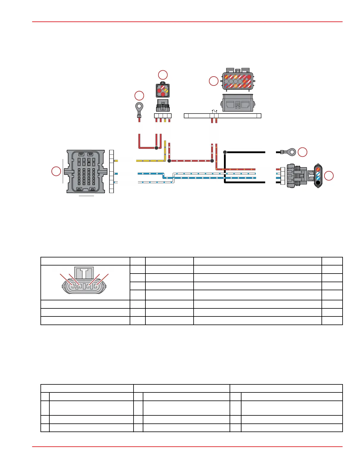
a - Hot stud (battery +)
b - Main power relay (MPR)
c - Fuse block: 2‑amp fuse
d - Chassis ground (–)
e - Diagnostic (RS48) connector
f - PCM connector A
Connector Pin Wire Color Function PCM
A Black Chassis ground (–) –
B Blue/white Serial communications + AE3
C White/blue Serial communications – AE4
D Red/orange Fused (2 A) 12 V power (+) –
Hot stud ring terminal – Red 12 V battery power (+) –
MPR 86 Yellow/purple Main power relay (MPR) control signal AA2
MPR 87 Red/white Switched 12 V power (+) –
Battery Isolator Troubleshooting
Battery isolators allow a single alternator to charge two batteries, while ensuring that the engine essential loads are isolated to
the engine starting battery. Vessel or "house" loads are isolated to the house battery. This makes certain that the engine
starting battery will have a sufficient charge to start the engine even if the house battery was depleted. Battery isolators also
ensure that the starting battery receives a charge from the alternator while the engine is running, and excess available charge
from the alternator is directed to the house battery. If the engine alternator is functioning correctly but one or both batteries fail
to receive a charge, then perform the following test of the battery isolator.
Engine Off Test
Engine Key On Test Engine Running Test
1. Turn off the battery charger. 1. Turn off the battery charger. 1. Turn off the battery charger.
2.
Disable any parallel switches or
VSR's.
2.
Disable any parallel switches or
VSR's.
2. Disable any parallel switches or VSR's.
3. Turn on the engine battery switch. 3. Turn on the engine battery switch. 3. Turn on the engine battery switch.
4. Turn on the house battery switch. 4. Turn on the house battery switch. 4. Turn on the house battery switch.
104B
105C
105B
109B
WHT/BLU
BLU/WHT
BLK
RED/ORN
RED/ORN
RED/WHT
BLK
WHT/BLU
BLU/WHT
RED/WHT
RED
RED
RED
YEL/PPL
YEL/PPL
2A
A1 B1 B2
C6
A
B
C
D
B1 B2 B3 B4 B5 B6
C1
C2
C3
C4 C5
A1 A2 A3 A4 A5 A6
C6
Accessories
90-8M0146617 eng JULY 2018 © 2018 Mercury Marine Page 5C-9
 Loading...


