Starting System Electrical Checks
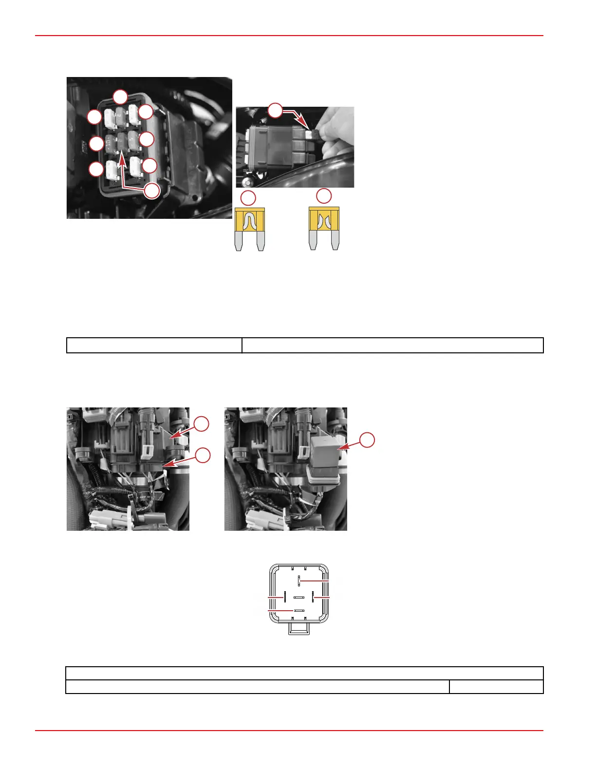
1. Inspect the 20‑amp driver power fuse.
a - Ignition coils ‑ 20 amp
b - Oxygen sensor ‑ 10 amp
c - Fuel pump ‑ 20 amp
d - Diagnostics ‑ 2 amp
e - Fuel injectors ‑ 20 amp
f - Advanced sound control ‑ 5 amp (V8
only)
g - Driver power (starter relay, fuel pump
relay, PCM drivers)
h - TVM power ‑ 15 amp (DTS models only)
i - Spare fuses (3)
j - Good fuse
k - Open fuse
2. Inspect the 5‑amp clean power fuse located near the engine starting battery.
3. The battery must deliver a minimum of 11 VDC to the starter. Perform a load test on the battery following the instructions
supplied with the load tester.
4. Install the shunt tool to the engine harness 14‑pin connector and perform the Smart Start test in the Diagnostic screen of
the CDS G3. If the starter engages, the problem lies in the hull wiring or helm harness. Refer to the preceding Starting
System Components and Connections diagrams. If the starter does not engage, continue to step 5.
12 Volt Shunt Tool
91‑889675A01
5. Inspect all connections at the battery, start relay, starter solenoid, starter motor, PCM, and the 14‑pin engine wiring
harness connector for tightness and corrosion. Clean or repair as necessary.
6. Remove the start relay and socket from behind the electrical panel (press the tab to release), and remove the relay from
the socket.
a - Electrical panel
b - Start relay socket on the engine
harness
c - Start relay
7. Measure the resistance of the relay's coil, between terminal 86 and terminal 85. Replace the relay, if the coil's resistance is
not within specification.
Four-pin relay pin identification
Start Relay
Coil resistance (terminal 86 to terminal 85) 80–100 Ω
Charging and Starting System
Page 6B-12 © 2018 Mercury Marine 90-8M0146617 eng JULY 2018
 Loading...


