Crankshaft Position Sensor (CPS)
The crankshaft position sensor (CPS) contains a magnet that is positioned next to the flywheel's lower ring gear. This ring gear
has 58 teeth with one gap (two missing teeth). The close proximity of the CPS magnet to the 58 teeth creates a magnetic field
each time a tooth passes in front of the sensor. As each tooth moves away, the field collapses. The expanding and collapsing
magnetic field creates a pulsating voltage, which is sent to the PCM. The PCM regulates ignition and fuel injector timing, based
on the timing and frequency of the pulses.
If the crankshaft position sensor fails, the engine will not start. The PCM will generate and store a fault code.
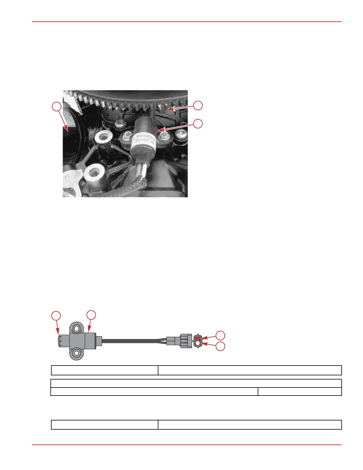
The CPS is located at the top of the cylinder block underneath the alternator bracket, near the oil filter.
Alternator bracket removed for clarity
a - Oil filter
b - Lower ring gear on flywheel
c - Crankshaft position sensor
CPS Test
1. Perform a visual inspection of the sensor. The tip of the sensor must be flush across the end. If it is not, replace the sensor.
2. The tip of the sensor must be clean. There should be no metal debris (ring gear filings) on the sensor tip.
NOTE: There is a magnet mounted in the sensor's tip. If the magnet is missing, the sensor will not operate properly.
3. Inspect the flywheel timing ring to ensure:
• Absence of corrosion
• Square edges on the teeth
• Only one gap of two missing teeth
Replace the flywheel if it does not meet inspection requirements.
4. Disconnect the sensor harness from the engine harness.
5. Perform a visual inspection of the sensor connector pins and the wires between the sensor and the connector. Look for
broken, bent, or corroded pins at the sensor and loose, broken, or corroded wires at the connector.
6. Measure the resistance across the sensor pins. Replace the sensor if it is out of specification.
a - Magnet
b - CPS
c - Pin 1 (red)
d - Pin 2 (white)
DMT 2004 Digital Multimeter 91‑892647A01
Crankshaft Position Sensor
Resistance at 21 °C (70 °F) 300–350 Ω
7. Connect the sensor harness to the engine harness, disconnect connector A from the PCM, and measure the resistance
across pins C4 and D4 of the connector. Resistance must be within specification. If not, repair the wiring between the PCM
and the sensor.
DMT 2004 Digital Multimeter
91‑892647A01
Sensors
90-8M0146617 eng JULY 2018 © 2018 Mercury Marine Page 5A-15
 Loading...


