Trim Down Circuit
When contact 86 of the trim down relay is energized from the trim switch, the trim down relay is energized. Contacts 30 and 87
of the trim down relay close, completing the circuit to 12 volts (+) to the green trim motor lead. The trim up relay remains
de‑energized. The trim motor tilts the engine down.
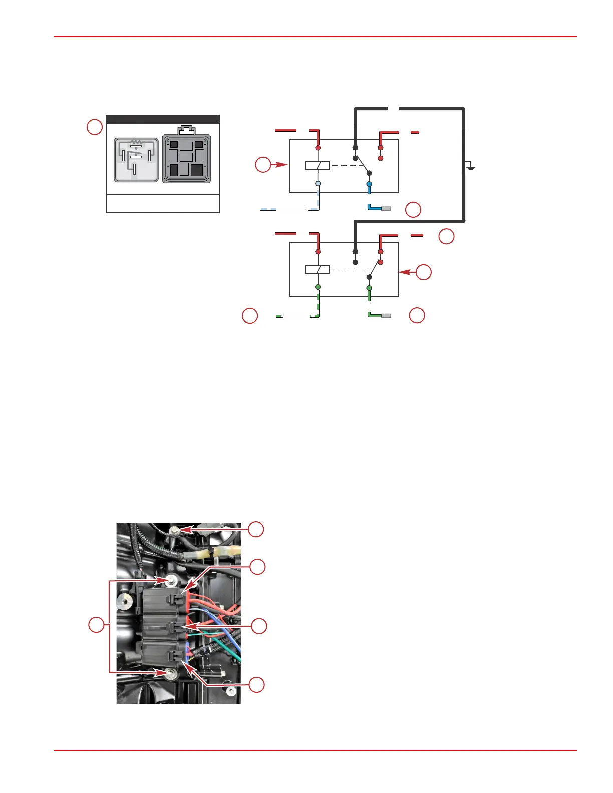
Trim down circuit
a - Trim relay contacts
b - Trim up relay
c - To trim motor (–)
d - 12 volts (+)
e - Trim down relay
f - To trim motor (+)
g - From PCM
Power Trim Relay Test
IMPORTANT: The starboard intake plenum must be removed to access the power trim relays. Refer to the appropriate service
manual for instructions.
IMPORTANT: To remove the power trim relays, press the relay lock tab with your finger and pull the relay out of the bracket.
Do not pull with the wires.
a - Trim relay ground wire screw
b - Trim up relay
c - Trim down relay
d - Main power relay
e - Relay bracket screws
The trim motor relay system, used on permanent magnet trim systems, connects each of the two wires from the trim motor to
either ground or positive to allow the motor to run in both directions.
85
86
30
87
87a
85
86
30
87
87a
GRN
BLU
RED
RED
BLK
(+)
(+)
(+)
67466
g
d
c
f
b
e
(–)
GRN/WHT
LT BLU/WHT
RED
(+)
RED
(+)
86
30
87
85
87a
87
87a
86
85
30
RELAY KEY
Relay Components
as Viewed Separated
Relay
Connector
Conventional Midsection (CMS) Power Trim
90-8M0146617 eng JULY 2018 © 2018 Mercury Marine Page 6C-11
 Loading...


