Home
Midea
Air Conditioner
V6R VRF Series
Midea V6R VRF Series User Manual
4
of 1
of 1 rating
167 pages
Give review
Manual
Specs
To Next Page
To Next Page
To Previous Page
To Previous Page
Loading...
V6R VRF 50
Hz
162
Midea
V
6R
Series Service Manual
4
Appendix to P
art 6
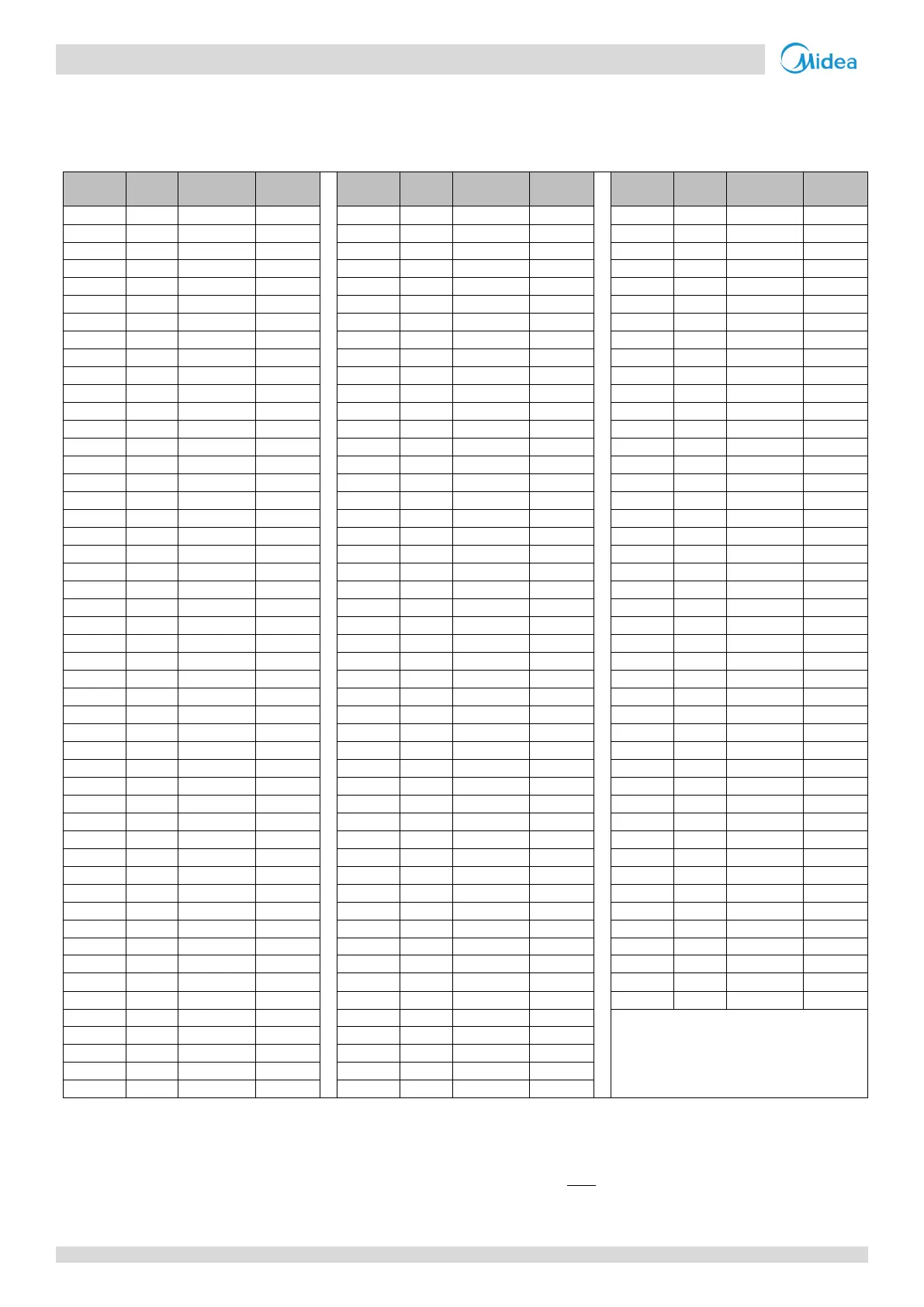
4.1
T
emperature Se
nsor Resis
tance Char
acterist
ics
T
able 6-4.1: T
emperature sensor resis
tance characteristi
cs
Temp.
(°
C)
Temp.
(°
F)
Resistance
(KΩ)
Voltage
(V)
Temp.
(°
C)
Temp.
(°
F)
Resistance
(KΩ)
Voltage
(V)
Temp.
(°
C)
Temp.
(°
F)
Resistance
(KΩ)
Voltage
(V)
-
39
-38.2
387.13
0.1020
11
51.8
19.617
1.4561
61
141.8
2.2728
3.9002
-
38
-36.4
360.98
0.1092
12
53.6
18.656
1.5085
62
143.6
2.1912
3.9312
-
37
-34.6
336.73
0.1169
13
55.4
17.749
1.5615
63
145.4
2.113
3.9615
-
36
-32.8
314.24
0.1250
14
57.2
16.891
1.6152
64
147.2
2.0381
3.9908
-
35
-
31
293.38
0.1337
15
59
16.08
1.6694
65
149
1.9662
4.0195
-
34
-29.2
274.01
0.1429
16
60.8
15.313
1.7242
66
150.8
1.8973
4.0473
-
33
-27.4
256.05
0.1526
17
62.6
14.587
1.7795
67
152.6
1.8312
4.0743
-
32
-25.6
239.36
0.1629
18
64.4
13.899
1.8352
68
154.4
1.7678
4.1006
-
31
-23.8
223.87
0.1738
19
66.2
13.249
1.8912
69
156.2
1.707
4.1261
-
30
-
22
209.48
0.1853
20
68
12.632
1.9476
70
158
1.6486
4.1510
-
29
-20.2
196.11
0.1974
21
69.8
12.048
2.0042
71
159.8
1.5925
4.1751
-
28
-18.4
183.68
0.2102
22
71.6
11.495
2.0609
72
161.6
1.5387
4.1985
-
27
-16.6
172.12
0.2237
23
73.4
10.97
2.1177
73
163.4
1.487
4.2212
-
26
-14.8
161.36
0.2379
24
75.2
10.472
2.1746
74
165.2
1.4373
4.2433
-
25
-
13
151.344
0.2528
25
77
10
2.2315
75
167
1.3896
4.2647
-
24
-11.2
142.02
0.2685
26
78.8
9.5519
2.2882
76
168.8
1.3437
4.2855
-
23
-9.4
133.32
0.2850
27
80.6
9.1265
2.3449
77
170.6
1.2996
4.3057
-
22
-7.6
125.22
0.3024
28
82.4
8.7226
2.4013
78
172.4
1.2572
4.3253
-
21
-5.8
117.66
0.3206
29
84.2
8.3389
2.4575
79
174.2
1.2164
4.3444
-
20
-4
110.6
0.3396
30
86
7.9743
2.5134
80
176
1.1772
4.3628
-
19
-2.2
104.02
0.3596
31
87.8
7.6279
2.5689
81
177.8
1.1394
4.3807
-
18
-0.4
97.861
0.3805
32
89.6
7.2985
2.6240
82
179.6
1.103
4.3981
-
17
1.4
92.107
0.4023
33
91.4
6.9853
2.6786
83
181.4
1.0681
4.4149
-
16
3.2
86.727
0.4252
34
93.2
6.6873
2.7327
84
183.2
1.0344
4.4313
-
15
5
81.694
0.4490
35
95
6.4038
2.7863
85
185
1.0019
4.4472
-
14
6.8
76.982
0.4739
36
96.8
6.134
2.8392
86
186.8
0.9707
4.4626
-
13
8.6
72.57
0.4998
37
98.6
5.8772
2.8915
87
188.6
0.94059
4.4775
-
12
10.4
68.437
0.5268
38
100.4
5.6326
2.9432
88
190.4
0.91158
4.4920
-
11
12.2
64.564
0.5549
39
102.2
5.3996
2.9941
89
192.2
0.88362
4.5060
-
10
14
60.932
0.5841
40
104
5.1776
3.0444
90
194
0.85667
4.5196
-9
15.8
57.526
0.6145
41
105.8
4.966
3.0938
91
195.8
0.83068
4.5328
-8
17.6
54.33
0.6459
42
107.6
4.7644
3.1424
92
197.6
0.80561
4.5457
-7
19.4
51.331
0.6786
43
109.4
4.5721
3.1903
93
199.4
0.78143
4.5581
-6
21.2
48.514
0.7123
44
111.2
4.3887
3.2373
94
201.2
0.75811
4.5701
-5
23
45.869
0.7473
45
113
4.2137
3.2834
95
203
0.7356
4.5818
-4
24.8
43.383
0.7834
46
114.8
4.0468
3.3287
96
204.8
0.71387
4.5932
-3
26.6
41.047
0.8207
47
116.6
3.8874
3.3731
97
206.6
0.6929
4.6042
-2
28.4
38.85
0.8591
48
118.4
3.7353
3.4166
98
208.4
0.67266
4.6149
-1
30.2
36.784
0.8987
49
120.2
3.59
3.4592
99
210.2
0.6531
4.6252
0
32
34.84
0.9394
50
122
3.4512
3.5009
100
212
0.63422
4.6353
1
33.8
33.011
0.9812
51
123.8
3.3186
3.5417
101
213.8
0.61598
4.6450
2
35.6
31.288
1.0242
52
125.6
3.1919
3.5816
102
215.6
0.59836
4.6545
3
37.4
29.666
1.0682
53
127.4
3.0708
3.6206
103
217.4
0.58133
4.6636
4
39.2
28.137
1.1134
54
129.2
2.955
3.6586
104
219.2
0.56487
4.6725
5
41
26.697
1.1595
55
131
2.8442
3.6958
105
221
0.54896
4.6812
6
42.8
25.339
1.2066
56
132.8
2.7382
3.7321
7
44.6
24.058
1.2547
57
134.6
2.6369
3.7674
8
46.4
22.85
1.3038
58
136.4
2.5398
3.8020
9
48.2
21.71
1.3537
59
138.2
2.4469
3.8356
10
50
20.633
1.4045
60
140
2.358
3.8683
Note
s:
1.
T
able 6-4.1 is suit
able f
or the fol
lowing sensors:
Outdo
or unit: T3, T4, T5, T6A, T6B
, T7, T8, T9, TL
MS: T1C1, T2C2
Indoor uni
t: T1, T2, T2A, T2B
2.
The Resi
st
ance of 25C (77F) is 10 KΩ±1%. The r
ela
tion betwee
n volt
age and resi
stance is: V
=
8.
06
8.
06
+R
*5
162
164
Table of Contents
Front Cover
1
CONTENTS
2
Part 1 General Information
4
1 Indoor and Outdoor Unit Capacities
5
1.1 Indoor Units
5
1.1.1 VRF indoor units
5
1.1.2 Fresh air processing unit
6
1.2 Heat recovery ventilator
6
1.3 High Temperature Hydro Module
6
1.4 Outdoor Units
6
2 External Appearance
7
2.1 Indoor Units
7
2.1.1 Fresh air processing unit
7
2.2 Heat Recovery Ventilator
8
2.3 High Temperature Hydro Module
8
2.4 Outdoor Units
9
2.4.1 Single units
9
2.4.2 Combinations of units
9
2.5 Mode Selection Box
10
3 Outdoor Unit Combinations
11
4 Combination Ratio
12
Part 2 Component Layout and Refrigerant Circuits
14
1 Layout of Functional Components
15
2 Piping Diagrams
17
3 Refrigerant Flow Diagrams
20
Part 3 Control
26
1 General Control Scheme Flowchart
27
2 Stop Operation
28
3 Standby Control
29
3.1 Crankcase Heater Control
29
4 Startup Control
29
4.1 Startup Sequence and Frequency Control in Combination Modules
29
4.2 Compressor Startup Delay Control
29
4.3 Startup Control for Cooling Only/Main Cooling Operation
30
4.4 Startup Control for Heating Only/Main Heating Operation
31
5 Normal Operation Control
32
5.1 Component Control During Normal Operation
32
5.2 Compressor Control
34
5.3 Rotation of Compressors
35
5.4 Heat Exchanger Control
35
5.5 Electronic Expansion Valve Control
36
5.6 Outdoor Fan Control
37
6 Protection Control
38
6.1 High Pressure Protection Control
38
6.2 Low Pressure Protection Control
38
6.3 Discharge Temperature Protection Control
39
6.4 Over-current Protection Control
39
6.5 Ambient temperature out of range protection control
40
6.6 Inverter Module Temperature Protection Control
40
6.7 Wet Compression Protection Control
41
6.8 High Pressure Ratio Protection Control
41
7 Special Control
42
7.1 Oil Return Operation
42
7.2 Defrosting Operation
44
8 Other Control
47
8.1 Overload control
47
8.2 Pump-down Control
47
8.3 Auto Snow-blowing Control
49
8.4 Auto Mode and Dual Set Points
49
8.5 Low Noise Mode
51
8.6 Power Limitation Mode
51
Part 4 Field Settings
52
1 Outdoor Unit Field Settings
53
1.1 PCB Switches and Switch Settings
53
1.2 Modes Set on Main PCB
55
1.2.1 Night silent mode setting
55
1.2.2 Silent mode setting
55
2 Mode Selection Box Field Settings
56
2.1 MS01 Switches Settings
56
2.2 MS04-12 Switches Settings
57
2.3 Manually Address Setting
57
Part 5 Electrical Components and Wiring Diagrams
58
1 Outdoor Unit Electric Control Box Layout
59
2 Outdoor Unit Main PCB
61
2.1 Ports
61
2.2 Components
63
2.2.1 Layout
63
2.2.2 Function of buttons SW3 to SW6
63
2.2.3 Menu mode
64
2.2.4 UP / DOWN system check button
66
2.2.5 Digital display output
68
3 Data Transfer Module
69
3.1 Layout
69
3.2 PCB components
69
3.3 Main functions
69
3.3.1 System check
69
3.3.2 Sync information from main PCB digital display
70
3.3.3 Auto snow-blowing setting
70
3.3.4 Data acquisition
70
3.3.5 Fault data storage
70
3.3.6 Data reading
70
3.3.7 Menu mode setting
70
4 Compressor Inverter Module
71
4.1 Ports
71
4.2 LED Indicators
74
5 Fan Module
75
6 Mode Selection Box Main PCB
76
6.1 Ports
76
6.2 Spot Check
78
7 Wiring Diagrams
79
Part 6 Diagnosis and Troubleshooting
84
1 Error Code Table
85
2 Troubleshooting for Outdoor Unit
88
2.1 Warning
88
2.2 E0: Communication error between outdoor units
88
2.2.1 Digital display output
88
2.2.2 Description
88
2.2.3 Trigger / recover condition
88
2.2.4 Possible causes
88
2.2.5 Procedure
89
2.3 E2: Communication error between MS box and master unit
90
2.3.1 Digital display output
90
2.3.2 Description
90
2.3.3 Trigger / recover condition
90
2.3.4 Possible causes
90
2.3.5 Procedure
91
2.4 E4: T3/T4 Temperature sensor error
92
2.4.1 Digital display output
92
2.4.2 Description
92
2.4.3 Trigger / recover condition
92
2.4.4 Possible causes
92
2.4.5 Procedure
92
2.5 E5: Abnormal power supply voltage
93
2.5.1 Digital display output
93
2.5.2 Description
93
2.5.3 Trigger / recover condition
93
2.5.4 Possible causes
93
2.5.5 Procedure
94
2.6 E7: Discharge Temperature sensor error (T7C1)
95
2.6.1 Digital display output
95
2.6.2 Description
95
2.6.3 Trigger / recover condition
95
2.6.4 Possible causes
95
2.6.5 Procedure
95
2.7 E8: Outdoor unit address error
96
2.7.1 Digital display output
96
2.7.2 Description
96
2.7.3 Trigger / recover condition
96
2.7.4 Possible causes
96
2.7.5 Procedure
96
2.8 E9: EEPROM mismatch of compressor
97
2.8.1 Digital display output
97
2.8.2 Description
97
2.8.3 Trigger / recover condition
97
2.8.4 Possible causes
97
2.8.5 Procedure
97
2.9 F1: DC bus voltage error
98
2.9.1 Digital display output
98
2.9.2 Description
98
2.9.3 Trigger / recover condition
98
2.9.4 Possible causes
98
2.9.5 Procedure
98
2.10 F3, F5, F9, FA, Fb, Fc, Fd: T6B/T6A/T5/T8/T9/TL/T7 Temperature sensor error
99
2.10.1 Digital display output
99
2.10.2 Description
99
2.10.3 Trigger / recover condition
99
2.10.4 Possible causes
99
2.10.5 Procedure
100
2.11 zF6: Electronic expansion valve connection error
101
2.11.1 Digital display output
101
2.11.2 Description
101
2.11.3 Trigger / recover condition
101
2.11.4 Possible causes
101
2.11.5 Procedure
102
2.12 H0: Communication error between main board and compressor drive board
103
2.12.1 Digital display output
103
2.12.2 Description
103
2.12.3 Trigger / recover condition
103
2.12.4 Possible causes
103
2.12.5 Procedure
104
2.13 H2, H3: Qty. of outdoor unit decreases/ increases error
105
2.13.1 Digital display output
105
2.13.2 Description
105
2.13.3 Trigger / recover condition
105
2.13.4 Possible causes
105
2.13.5 Procedure
106
2.14 H4: Compressor inverter module protection
107
2.14.1 Digital display output
107
2.14.2 Description
107
2.14.3 Trigger / recover condition
107
2.14.4 Possible causes
107
2.14.5 Specific error codes for H4 inverter module protection
107
2.14.6 L0: Inverter module protection
109
2.14.7 L1: DC bus low voltage protection
110
2.14.8 L2: DC bus high voltage protection
111
2.14.9 L5: Zero speed protection
112
2.14.10 L7: Phase sequence error
113
2.14.11 LA: PED software verification failed
114
2.14.12 Compressor replacement procedure
115
2.15 H7: Qty. of indoor units mismatching
118
2.15.1 Digital display output
118
2.15.2 Description
118
2.15.3 Trigger / recover condition
118
2.15.4 Possible causes
118
2.15.5 Procedure
119
2.16 H8: High pressure sensor error
120
2.16.1 Digital display output
120
2.16.2 Description
120
2.16.3 Trigger / recover condition
120
2.16.4 Possible causes
120
2.16.5 Procedure
121
2.17 Hb: Low pressure sensor error
122
2.17.1 Digital display output
122
2.17.2 Description
122
2.17.3 Trigger / recover condition
122
2.17.4 Possible causes
122
2.17.5 Procedure
123
2.18 yHd: Slave unit malfunction
124
2.18.1 Digital display output
124
2.18.2 Description
124
2.18.3 Trigger / recover condition
124
2.18.4 Possible causes
124
2.18.5 Procedure
124
2.19 P1: High pressure protection
125
2.19.1 Digital display output
125
2.19.2 Description
125
2.19.3 Trigger / recover condition
125
2.19.4 Possible causes
125
2.19.5 Procedure
126
2.20 P2, H5: Suction pipe low pressure protection
127
2.20.1 Description
127
2.20.2 Trigger / recover condition
127
2.20.3 Possible causes
127
2.20.4 Procedure
128
2.21 P31: Primary current protection
129
2.21.1 Digital display output
129
2.21.2 Description
129
2.21.3 Trigger / recover condition
129
2.21.4 Possible causes
129
2.21.5 Procedure
129
2.22 P32: Secondary current protection
131
2.22.1 Digital display output
131
2.22.2 Description
131
2.22.3 Trigger / recover condition
131
2.22.4 Possible causes
131
2.22.5 Procedure
131
2.23 P4, H6: Discharge temperature protection or discharge temperature switch protection
133
2.23.1 Digital display output
133
2.23.2 Description
133
2.23.3 Trigger / recover condition
133
2.23.4 Possible causes
133
2.23.5 Procedure
134
2.24 P9, H9: Fan module protection
136
2.24.1 Digital display output
136
2.24.2 Description
136
2.24.3 Trigger / recover condition
136
2.24.4 Possible causes
136
2.24.5 Procedure
137
2.25 PL, C7: Inverter module temperature protection
138
2.25.1 Digital display output
138
2.25.2 Description
138
2.25.3 Trigger / recover condition
138
2.25.4 Possible causes
138
2.25.5 Procedure
138
2.26 PP: Compressor discharge insufficient superheat protection
139
2.26.1 Digital display output
139
2.26.2 Description
139
2.26.3 Trigger / recover condition
139
2.26.4 Possible causes
139
2.26.5 Procedure
140
2.27 A0: Emergency shutdown
141
2.27.1 Digital display output
141
2.27.2 Description
141
2.27.3 Trigger / recover condition
141
2.27.4 Possible causes
141
2.27.5 Procedure
142
2.28 A1w: Refrigerant leakage protection
143
2.28.1 Digital display output
143
2.28.2 Description
143
2.28.3 Trigger / recover condition
143
2.28.4 Possible causes
143
2.28.5 Procedure
143
2.29 CA1, CA2, CA3, CA4, CA5: Connection combination error
144
2.29.1 Digital display output
144
2.29.2 Description
144
2.29.3 Trigger / recover condition
144
2.29.4 Possible causes
144
2.29.5 Procedure
144
2.30 CB1, CB2, CB3, CB4: Overmatch protection
145
2.30.1 Digital display output
145
2.30.2 Description
145
2.30.3 Trigger / recover condition
145
2.30.4 Possible causes
145
2.30.5 Procedure
145
2.31 U0: Force cooling operation not performed
146
2.31.1 Digital display output
146
2.31.2 Description
146
2.31.3 Trigger / recover condition
146
2.31.4 Possible causes
146
2.31.5 Procedure
146
2.32 U21, U22, U23: Ambient temperature is out range of test operation.
147
2.32.1 Digital display output
147
2.32.2 Description
147
2.32.3 Trigger / recover condition
147
2.32.4 Possible causes
148
2.32.5 Procedure
148
2.33 U31, U32, U33: Stop valve is not open.
149
2.33.1 Digital display output
149
2.33.2 Description
149
2.33.3 Trigger / recover condition
149
2.33.4 Possible causes
149
2.33.5 Procedure
149
2.34 U4: Indoor unit refrigerant pipe and signal cable connection are inconsistent
150
2.34.1 Digital display output
150
2.34.2 Description
150
2.34.3 Trigger / recover condition
150
2.34.4 Possible causes
150
2.34.5 Procedure
150
3 Troubleshooting for Mode Selection Box
151
3.1 Warning
151
3.2 E2: Communication error between MS and master outdoor unit
151
3.2.1 Digital display output
151
3.2.2 Description
151
3.2.3 Trigger / recover condition
151
3.2.4 Possible causes
151
3.2.5 Procedure
152
3.3 E3/E4: T1C1/T2C2 Temperature sensor error
153
3.3.1 Digital display output
153
3.3.2 Description
153
3.3.3 Trigger / recover condition
153
3.3.4 Possible causes
153
3.3.5 Procedure
153
3.4 E7: EEPROM error
154
3.4.1 Digital display output
154
3.4.2 Description
154
3.4.3 Trigger / recover condition
154
3.4.4 Possible causes
154
3.4.5 Procedure
154
3.5 FE: MS has no address when first powered on
155
3.5.1 Digital display output
155
3.5.2 Description
155
3.5.3 Trigger / recover condition
155
3.5.4 Possible causes
155
3.5.5 Procedure
155
3.6 LL: S1+S2 dialing setting error (for MS04-12)
156
3.6.1 Digital display output
156
3.6.2 Description
156
3.6.3 Trigger / recover condition
156
3.6.4 Possible causes
156
3.6.5 Procedure
156
3.7 H0: Communication between master and slave control boards failed (for MS04-12)
157
3.7.1 Digital display output
157
3.7.2 Description
157
3.7.3 Trigger / recover condition
157
3.7.4 Possible causes
157
3.7.5 Procedure
157
3.8 F6: Electronic ball valve connection failure (for MS01)
158
3.8.1 Digital display output
158
3.8.2 Description
158
3.8.3 Trigger / recover condition
158
3.8.4 Possible causes
158
3.8.5 Procedure
159
3.9 F7: Main power off (for MS01)
160
3.9.1 Digital display output
160
3.9.2 Description
160
3.9.3 Trigger / recover condition
160
3.9.4 Possible causes
160
3.9.5 Procedure
160
3.10 F9: Overload error (for MS01)
161
3.10.1 Digital display output
161
3.10.2 Description
161
3.10.3 Trigger / recover condition
161
3.10.4 Possible causes
161
3.10.5 Procedure
161
3.11 A1: Refrigerant leakage protection (for MS01)
162
3.11.1 Digital display output
162
3.11.2 Description
162
3.11.3 Trigger / recover condition
162
3.11.4 Possible causes
162
3.11.5 Procedure
162
4 Appendix to Part 6
163
4.1 Temperature Sensor Resistance Characteristics
163
4.2 Pressure Sensor Voltage Characteristics
165
4.3 Parameters of Excess and Insufficient Refrigerant System
166
Back Cover
167
4
Based on 1 rating
Ask a question
Give review
Questions and Answers:
Need help?
Do you have a question about the Midea V6R VRF Series and is the answer not in the manual?
Ask a question
Midea V6R VRF Series Specifications
General
Brand
Midea
Model
V6R VRF Series
Category
Air Conditioner
Language
English
Related product manuals
Midea V6R Series
131 pages
Midea VRF
106 pages
Midea Mini VRF
84 pages
Midea VRF Series
167 pages
Midea V8 VRF Series
109 pages
Midea V5 X VRF Series
169 pages
Midea Mini VRF C Series
12 pages
Midea VRF V4 Plus I Series
114 pages
Midea V6 Series
136 pages
Midea V6-i Series
118 pages
Midea MHC-V6W/D2N8-B
113 pages
Midea ATOM MDV-V60WDHN1(AtB)
86 pages

 Loading...