20
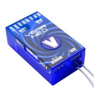
VBar NEO, VBar
and Mini VBar
☠ Danger An R/C controlled helicopter is not a toy! While
moving, the rotor blades pose a serious danger to persons
and things. You must obey all safety instructions of the
manufacturer for operation of your helicopter.
☝ Attention VBar is not an autopilot! VBar may be installed in
helicopters which are suitable for ying without ybar.
During installation and operation you must follow all in-
structions given in the software and in this manual. VBar
may not be operated in wet conditions (high humidity or
rain). If the helicopter shows vibrating behavior during
ight, operation of the helicopter is to be stopped immedi-
ately. Do not continue ying until the cause for vibration has
been eliminated.
⚠ Caution When setting up, disconnect the motor wires or
remove the pinion gear to avoid accidental spooling up of
the helicopter while setting up the speed controller (ESC)
functions. The same applies when loading unknown setup
or preset-les, as they may transport other settings as you
have on your heli!
☝ Attention Never connect the Gyro-Sensor to a port other that
it‘s own or it will be destroyed immediately and beyond repair.
☝ Attention Never connect power to RX A, RX A is signal
transmission-only.
☝ Attention A heli equipped with VBar draws higher currents
than a conventional ybarred heli. Make sure you use a
sufcient power supply.
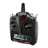
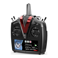
VBar Control Satellite AUX 2/3 (optional) CP Control Panel
Non-Mikado receiver (see manual
to the respective VBar)
AUX 1, TELE 1, TELE 2 RX A, RX B, RX C, RX-1, RX-2 AUX, Elevator, Aileron, Colle/ESC,
Rudd/AUX 2, RX1, RX2
Swash plate
(the actual assignment is shown in
the setup wizard)
CH1
CH2
CH3
CH4
CH1
CH2
CH3
Channel 1
Channel 2
Channel 3
Channel 4
Tail rotor servo TAIL RD Tail Servo
Electronic speed controller (ESC) ESC RX B Colle/ESC
Throttle servo (Nitro) ESC — Servo
RPM sensor
RX A (on a Mini VBar) and
Sensor II (one a full size VBar)
must not be used for power supply
to the VBar!
RPM
(has receiver voltage, so check if
your sensor can handle e.g. 8.4 V
/ 2S LiPo, else you might need a
voltage regulator (similar to the
one for a tail servo).
Signal lead (usually orange) to RX
A, upper pin; supply voltage e.g.
to RX C using a Y-harness.
Attention: do not apply more than
5 V on RX A, for higher receiver
voltage use a voltage divider.
Sensor II
If an rpm signal lead does
require 3.3-5 V receiver
voltage or also serves a BEC slave
wire (e.g. YGE ESCs), you can
(BEC: must) connect (+) and (–)
wire(s) to the front of the VBar.
Gyro sensor SENSOR (optional) — Gyro Sensor
Telemetry (only with VBar Control) TELE 1, TELE 2 RX-1, RX-2 RX1, RX2
☝ Attention polarity is always shown on the label of the VBar.
The brown lead (negative terminal) of the servo connectors
must point to the label. For extra connectors on e.g. VBar
Silverline, see the markings on the label, too.
☝ Attention Additional power supply may be connected to
any free port on the servo side (Mini VBar: do not use RX A
for power supply, if necessary use Y-harnesses).
☝ Attention USB is only used for rmware updates. Do not
connect at the same time with a VBar Control Satellite.
☝ Note: the remaining connectors may be used for special
functions (e.g. retractable landing gear, light). Information
will be provided in the relevant manuals to specic Apps.
You can download these manuals from www.vstabi.info.
☝ Attention If you chose to use a VBar with other radio con-
trol systems, please refer to the Quick Start Guide provided
on www.vstabi.info. You must install a different rmware on
the VBar for use with other radio control system.
☝ Attention When using Telemetry, do not connect a signal
wire (orange or white wire, e.g. from a slave power supply
wire of a BEC) to RX C (Mini VBar) or AUX (black, blue or
silver full size VBar), this might interfere with the telemetry
signal.