Pellerin Milnor Corporation 77
3. Use the adjusting nut (lower hex nut) to “crank” the shaft up or down as required.
4. Once final adjustment is made, while holding the adjusting nut to prevent it from turning, re-
tighten the lock nut against the adjusting nut (with the lock washer between).
5. Rebend the tongues on the lockwasher as before, to prevent movement of the nuts.
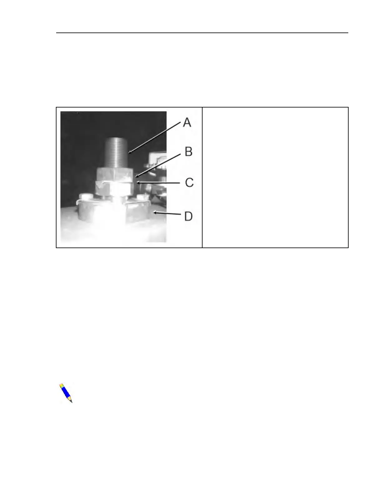
Figure 30. Hydro-cushion™ Upper Shaft and Adjusting Nuts
Legend
A...Hydro-cushion™shaft
B...Locknut
C...Keyed lockwasher
D...Adjusting nut
Shell Hanging Dimensions and Adjustment Procedures
BNWVUM01.T02 0000278201 A.3 B.2 2/5/21 9:25 AM Released
To adjust the shell of a divided cylinder machine, proceed as follows:
1. Locate the shell hanging dimension for your machine in Table 27: Hanging Dimensions, page
78 and adjust your machine accordingly. Take measurements on the left and right sides of the
shell, to assure that the shell is horizontal, left to right.
2. The shell and cylinder should be level front to back. Check this with a bubble level, as shown
in Figure 31: Shell Hanging for Divided Cylinder Machines (Left side view of 60044WE
shown), page 78 .
3. If further adjustment is required in order to level the cylinder, make small adjustments at all
four corners. For example, if the cylinder slopes down to the front, try raising the two front
corners by 1/16" (2mm) and lowering the two rear corners by 1/16" (2mm). Always split the
difference.
NOTE: Only slight deviations from the dimensions shown should be used to level the
shell. If large deviations are required, this may indicate that the frame is out of level. If so,
this condition must be corrected before attempting to level the shell.
Frame, Pivots, and Suspension
 Loading...