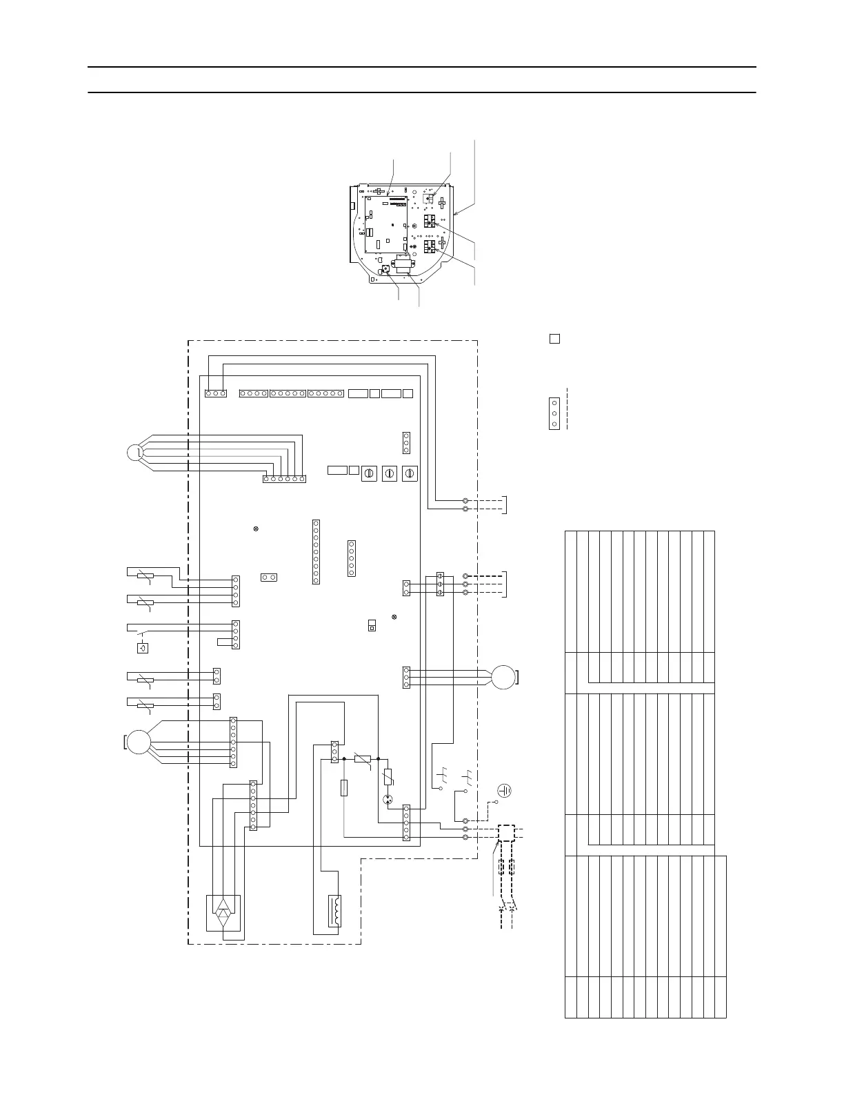
1. PEFY-P36, 48NMHU-E-OA
ON
CND
(Red)
INSIDE SECTION OF CONTROL BOX
SWE
TB2
13
CNP
LED1
POWER SUPPLY
~208,230V
60Hz
531
1
CN2M
(Blue)
2
1
CN3A
(Blue)
3
5
6
7
8
9
0
1
2
3
4
SW12
(10ths digit)
SW1
SW2
SW3
SW4
SW21
SW22
2
CN20
(Red)
1
2
CN44
143
1
CN60
2
3
4
5
6
LEV
S(SHEILD)
TH21 TH22TH23
TO NEXT INDOOR UNIT
BREAKER(16A) FUSE(16A)
PULL BOX
TO MA REMOTE
CONTROLLER
TO OUTDOOR UNIT
BC CONTROLLER
REMOTE CONTROLLER
CNACL
(Black)
SA
U
ZNR002
CN41
CN51
CN52
(Green)
CN32
CN105
(Red)
0
9
8
7
6
5
4
3
2
1
SW11
(1s digit)
0
8
7
6
5
4
3
2
1
SW14
(BRANCH No.)
F
E
D
C
B
A
9
21
21
3
CNE
(White)
3
2
CN22
(Green)
1
TH24
LED2
CN90
2
CN4F
143
FS
L1 L2 G
TB5
M1 M2
TB15
12
CN27
(Red)
7
CNMF1
41
MF
31
65
7
CNDB
531
1
2
3
4
DB
I.B.
OFF
MS
3~
M
MS
3~
DP
ACL
U
ZNR001
F1
PARTS LOCATION
ACL
SYMBOL
SYMBOL EXPLANATION
NAME
NOTE)1.Since the outdoor side electric wiring may change be sure
to check the outdoor unit electric wiring for servicing.
2.Symbols used in wiring diagram are
:Connector, :Terminal,
(Heavy dotted line):Field wiring,
3.Have all electric work done by a licensed electrician
according to the local regulations.
4.Earth leakage circuit breaker should be set up on the wiring
of the power supply.
5.To perform a drainage test for the drain pump turn on the SWE
on the control board while the indoor unit is being powered.
*Be sure to turn off the SWE after completing a drainage test or test run.
6.Use copper supply wires.
AC reactor(Power factor improvement)
Diode Bridge
Drain Pump
Float switch
Fan Motor
Power source terminal block
Transmission terminal block
Transmission terminal block
Thermistor (outlet air temp. detection)
Thermistor (piping temp.detection/liquid)
Thermistor (piping temp.detection/gas)
DB
DP
FS
MF
TB2
TB5
TB15
TH21
TH22
TH23
CN32
Connector (Remote switch)
CN41
Connector (HA terminal-A)
CN51
Connector (Centrally control)
CN52
Connector (Remote indication)
CN90
Connector (Wireless)
CN105
Connector (IT terminal)
SW2
Switch (for capacity code)
SW3
Switch (for mode selection)
SW14
Switch (BRANCH No.)
SW21
Switch (for static pressure selection)
SW22
Switch (Wireless pair No.)
SWE
Connector (emergency operation)
LED1
LED(Power supply)
LED2
LED(Remote controller supply)
SYMBOL NAME SYMBOL NAME
SA
Arrester
F1
Fuse AC250V 6.3A
ZNR001,002
Varistor
SW4
Switch (for model selection)
SW11
Switch (1s digit address set)
SW12
Switch (10ths digit address set)
I.B.
Indoor controller board
I.B.
Indoor controller board
Electrical linear expansion valve
LEV
Thermistor (inlet air temp. detection)
TH24
CN27
Connector (Damper output)
SW1
Switch (for mode selection)
I.B.
TB2 CONTROL BOXTB5
DB
ACL
TB15
t° t° t° t°
-
+
 Loading...