[ VIII Disassembly Procedure ]
- 32 -
HWE1804A GB
[2] Disassembly Procedure (PEFY-P72, 96NMHU-E-OA)
1. Control box
Be careful on removing heavy parts.
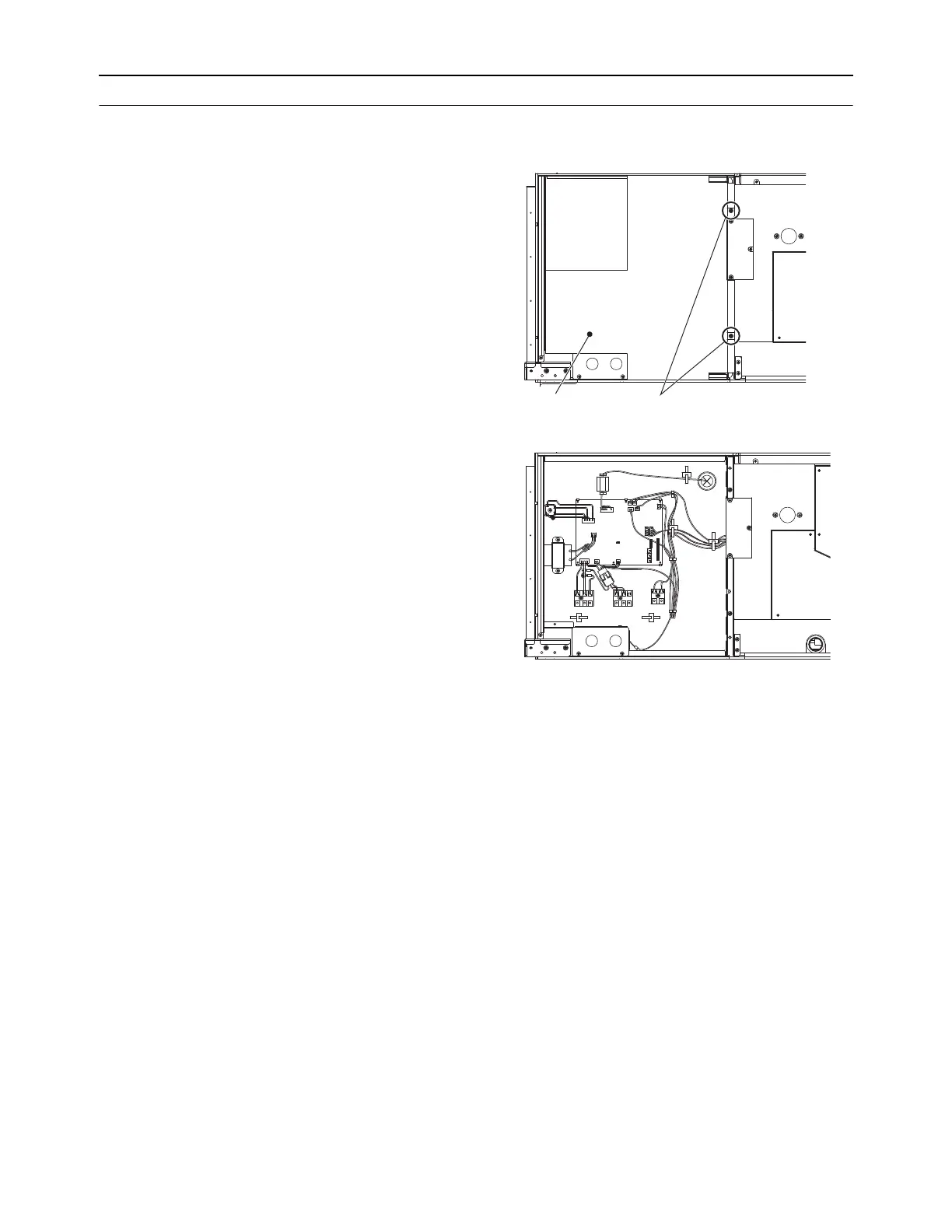
1. Removing the control box cover
(1) Remove the fixing screws (two) of the control box (A), and
remove the cover. (Fig.1)
*At this stage, the following servicing is possible. (Fig.2)
1) Operation and check of the switches (listed below) which
are on the control board.
Dip switch SW1 . . . . . . . . . . . . Function change
Dip switch SW2 . . . . . . . . . . . . Capacity code setting
Dip switch SW3 . . . . . . . . . . . . Function change
Dip switch SW4 . . . . . . . . . . . . Model code setting
Dip switch SW21 . . . . . . . . . . . Static pressure setting
Dip switch SW22 . . . . . . . . . . . Function setting
Rotary switches SW11, 12 . . . . Address setting
Rotary switch SW14 . . . . . . . . . Branch port setting
2) Connection check of the lead wires (listed below) which
are connected to the controller board.
Power supply lead wire.
Transmission lead wire x 2
Fan motor lead wire.
LEV lead wire
Inlet air temperature thermistor lead wire
Outlet air temperature thermistor
Liquid piping temperature thermistor lead wire
Gas piping temperature thermistor lead wire
Drain pump lead wire
Float switch lead wire
3) Control board exchange
4) Reactor exchange
5) Thermistor (inlet air, outlet air, liquid piping, gas piping)
exchange
6) Power supply terminal bed exchange
7) Transmission terminal bed exchange x 2
8) Ferrite core exchange
A ferrite core is attached to the wire only when the model
of fan motor is KMUC4E3MW. The model of the motor is
noted in the nameplate on the fan motor casing.
Fig.1
Fig.2
Fixing screws
(A)
 Loading...