-
107
-
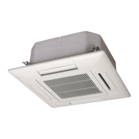
Liquid piping: φ6.35 (1/4")
(Flare connecting)
Gas piping: φ12.7 (1/2")
(Flare connecting)
Piping, wiring outlet
L2
L1
L3
Terminal block
Holes for drain
(φ20×5 pcs.)
Holes for anchor bolt
(M10×4 pcs.)
58.6
132
43.1
51.9
471.5
L4
42.5
96.5
595
14.4
29.7
90.6
50
12
510
2-R6
106
780
67
463
49.6
45.4
290
286.4
164
17.5
14
312.5
13.5
340
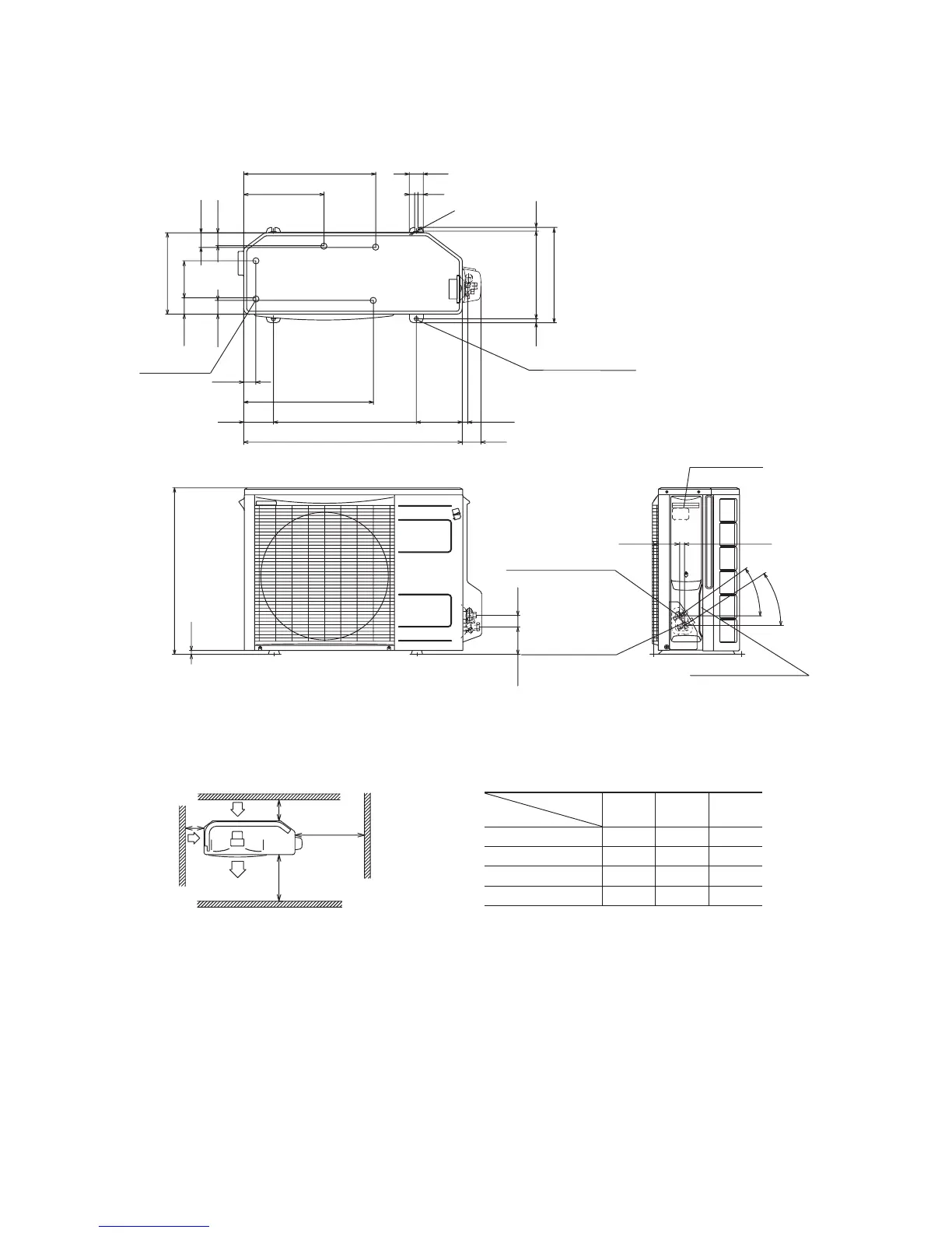
Air inlet
Air outlet
Maintenance
space
( )
Air
inlet
35˚
35˚
Required space for maintenance and air fl ow Minimum allowable space to the obstacles
Unit:mm
Notes
(1) It is prohibited to install in a space enclosed with walls at four
sides.
(2) Unit must be secured with anchor bolts.
Anchor bolt should not protrude more than 15 mm above the
surface.
(3) Where strong winds blow, the blow outlet must be oriented at
right angle against the wind direction.
(4) Secure a space of 1 m or more above the unit.
(5) Barrier standing in front of the blow outlet must be lower than the
height of unit.
Unit: mm
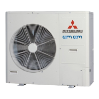
(3) Outdoor unit
Models FDCVA151HENR, 201HENR
Installation
type
Mark
123
L1 Open 280 280
L2 100 75 Open
L3 100 80 80
L4 250 Open 250
 Loading...