-
144
-
Thermo ON output(DC12V output)
Inspection output(DC12V output)
Remote operation input(volt-free contact)
Auxiliary relay(For DM)
Terminal block( mark)
Connector(
mark)
Closed-end connector
XR3
XR4
XR5
X4
TB
CnA~Z
mark
1
2/N
Y/GN Y/GN
RD
WH
CnW0
TB
TrI
Power source
220/240V
15V
17V
Printed circuid
board
F(3.15A)
F(0.16A)
BL
BL
RD
RD
CnH
CnH2
CnN3 CnN4
CnN1
ThI-A ThI-R2ThI-R1
X
Y
Z
X
Y
Z
RD
RD
WH
WH
BK
BK
CnB
Thc
TB
CnV
CnZ
Remote
controller
WH
WH
RD
BR
BR
BK
BL
CnM6
CnM4
CnM3
CnM5
CnM2
CnW2
CnW1
CnR
CnR2
DM
FMI
*1
SW9
SW5
SW2
LED·2
LED·1
X4
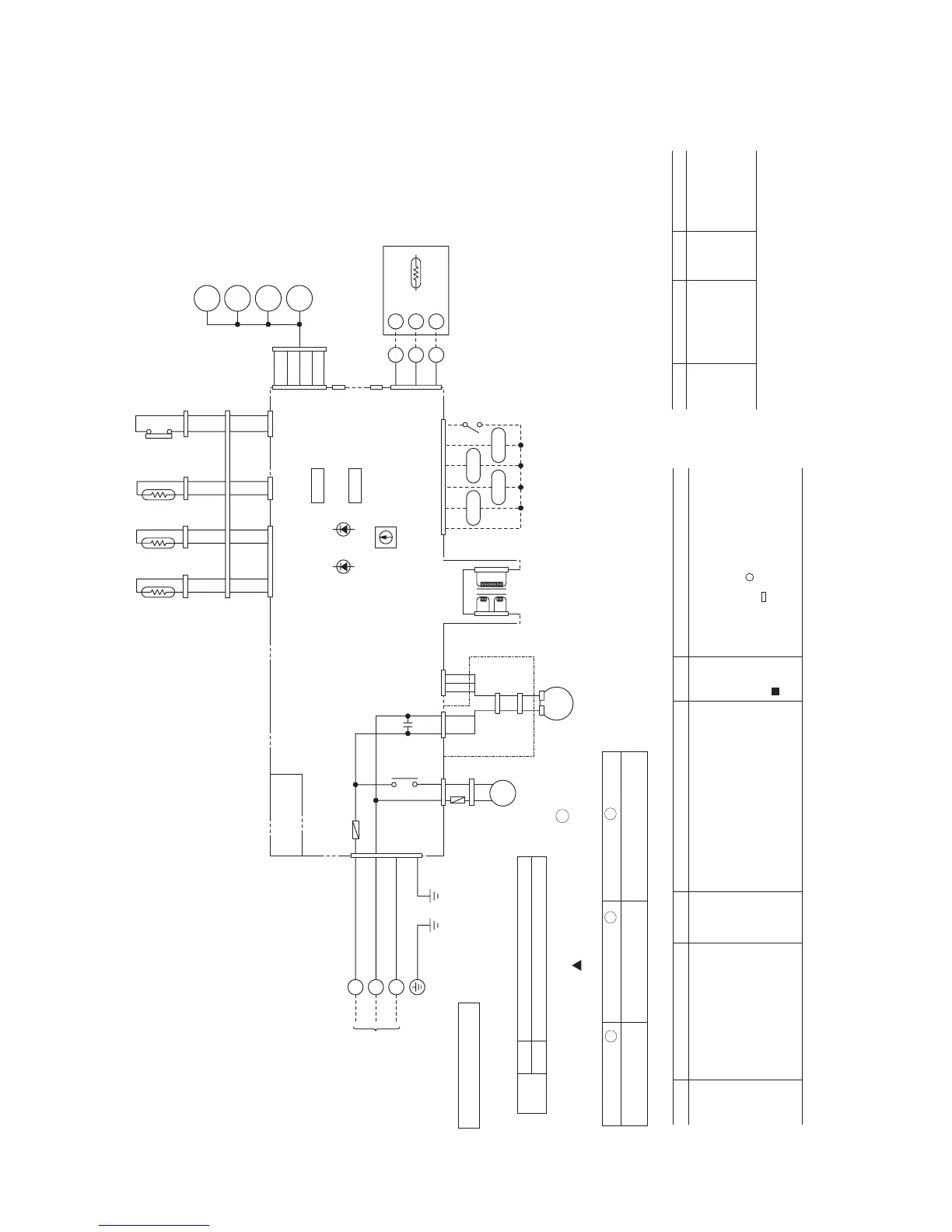
Note (1) Always turn off power before you unplug the fan motor connector shown in
an area *1 delineated by a dotted line, otherwise a breakdown of the fan motor
may result.
FMI
DM
FS
LM1~4
ThI-A
ThI-R1
ThI-R2
Thc
Fan motor
Drain motor
Float switch
Louver motor
Thermistor
Thermistor
Thermistor
Thermistor
SW2
SW9-3
TrI
F
LED1
LED2
XR1
XR2
Remote controller communications address setting
Emergency operation
Transformer
Fuse
Indication lamp(Red)
Indication lamp(Green)
Operation output(DC12V output)
Heating output(DC12V output)
Mark Parts nameMark Parts nameMark Parts name
Meaning of marks
Color marks
BK
BL
BR
OR
RD
Black
Blue
Brown
Orange
Red
WH
Y
P
Y/GN
White
Yellow
Pink
Yellow/Green
Mark Color Mark Color
3
1
1
234
CnM1
13
1
3
21
3
11234
5634
1212
2
78
12
1
2
3
5
CnT
XR1 XR3
XR2 XR4
XR5
Option
123456
Y
Y
BL
BL
RD
RD
Y
Y
12
12
12
BL
P
BR
OR
RD
CnJ
CnJ2
LM1
LM2
LM3
LM4
1
2
3
4
5
WH
WH
WH
WH
CnI
CnI2
CnC
FS
3
WH
7
Blower fan tap switch
SW9-4
ON
OFF
Fan control, powerful mode
Fan control, mild mode
Function number A Function description B Setting C
Set SW9-4 provided on the indoor unit PCB to OFF.
Use one of the two methods to set the fan tap.
01
Hi CEILING SET STANDARD
(Mild mode)
Select the “STANDARD (Mild mode)” setting for “ C ” in
#01 of “I/U FUNCTION ” (indoor unit function) by using
remote controller function setting.
1.3 ELECTRICAL DATA
1.3.1 Electrical wiring
(1) Indoor unit
(a) Ceiling recessed compact type (FDTC)
Models All models
 Loading...