-
151
-
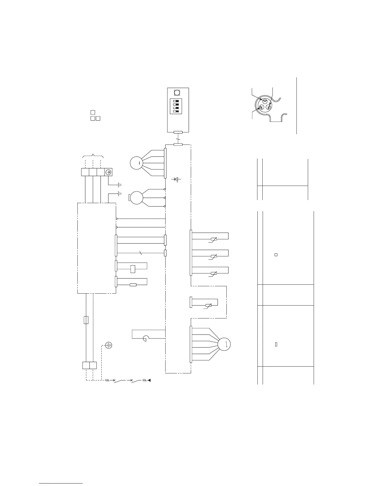
Printed circuit board
Sub printed circuit board
Position of compressor terminals
BK
W
RD
U
WH
V
To indoor unit
Power wires
Signal wire
1
3
2
1Phase
220-240V 50Hz/220V 60Hz
Power source
TB
RD
WH
TB
OR
GR
BR
Y/GN
Y/GNY/GN
RD
RD
BK
BK
BK
BL
BL
BR
BR
OR
WH
Y
OR
BL
BR
RD
Y
WH
BL
WH
BK
BK
BK
BK
BK
WH
Y
BL
Outdoor swith board
Compressor motor
CM
Connector( mark)
CNA
~
Z
Fuse
F
FMo
Fan motor(outdoor unit)
LED1
Indication lamp(Red)
CH
Crankcase heater
Mark
Color marks
Color
BK
BR
GR
RD
Black
BL Blue
Brown
Gray
OR Orange
Red
WH White
Y
Y/GN Yellow/Green
Yellow
Parts nameMark
Meaning of marks
Tho-A
Tho-D
Tho-R
TB Terminal block( mark)
SW5-1 Defrost control switch
SW5-2 Snow prevented fan control switch
SW5-4 Test run switch(Cooling/Heating)
SW5-3 Operate test run switch
SW9 Test run switch
SM Expansion valve(for EEV)
Thermistor(discharge temp.)
Tho-IPM Thermistor(Power transister temp.)
Thermistor(outdoor H.EX. temp.)
Thermistor(ambient air temp.)
Parts nameMark
20S Solenoid valve for 4 way valve
N
F5(20A)
L
T25
T26
T22
T21
T24
CNR
CH
CM
FMo
Inductor
20S
CNS CNI1
10
2/N
3
1
M
SM
52143
CNV1
6
T4T2
Tho-A
Tho-IPM
Tho-R Tho-D
CNM
T1T5
CNTR
21213
UVW
MS
3~
M
46
CNQ1
546
6
CNQ
123
LED1
CNI3CNI2
T30
T28 T27
CNL
SW9
SW5
32
ON
14
t˚
t˚
t˚
t˚
()
(2) Outdoor unit
Models FDCA151HENR,201HENR,251HENR
 Loading...