Mel
~
n
t
e
r
l
o
C
k
, ,
Power R U
'1M
su
P
P:;y1}
~
~
~~-~
Current
~
loop
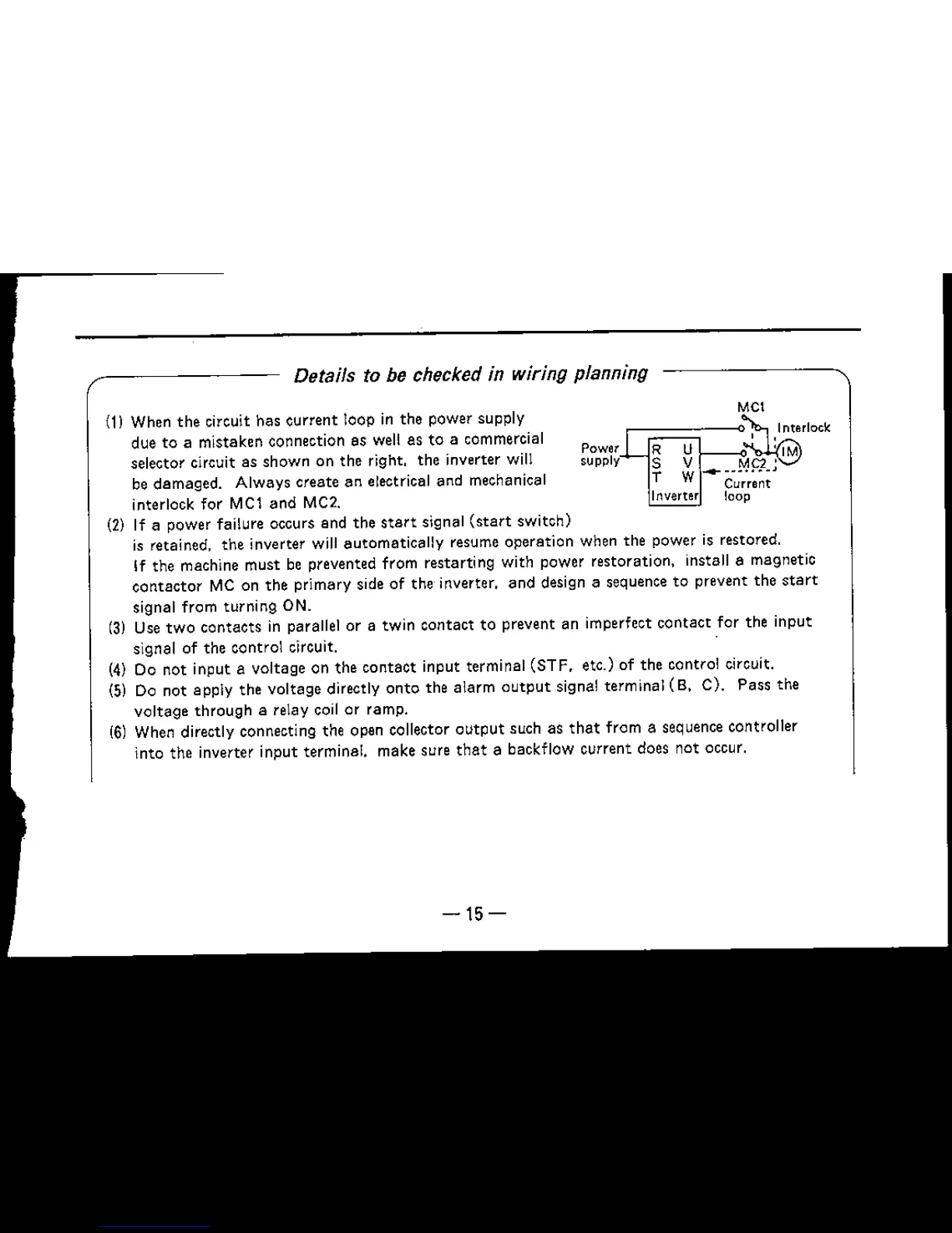
Details to be checked in wiring planning
(1) When
the
circuit has current loop in the power supply
due to a mistaken connection as well as to a commercial
selector circuit as shown on the right, the inverter will
be damaged. Always create an electrical and mechanical
interlock
for
MCl and MC2.
(2) If a power failure occurs and the
start signal
(start
switch)
is retained. the inverter will automatically resume operation when the power is restored.
If the machine must be prevented from restarting with power restoration, install a magnetic
ccntector
MC on the primary side of the inverter, and design a sequence to prevent the
start
signal from turning ON.
(3) Use
two
contacts
in parallel or a twin contact to prevent an imperfect
contact
for the input
signal of the control circuit.
(4) Do not input a voltage on the
contact
input terminal (STF, etc.) of the control circuit.
(5) Do not apply the voltage directly
onto
the alarm
output
signal terminal
(8,
C). Pass the
voltage
through
a relay coil or ramp.
(6) When directly connecting the open collector
output
such as
that
from a sequence controller
into the inverter input terminal. make sure
that
a backflow current does not occur.
-15-

 Loading...