432
FX3G/FX3U/FX3GC/FX3UC Series
Programming Manual - Basic & Applied Instruction Edition
15 External FX I/O Device – FNC 70 to FNC 79
15.6 FNC 75 – ARWS / Arrow Switch
15.6 FNC 75 – ARWS / Arrow Switch
Outline
This instruction inputs data through arrow switches used for shifting the digit and incrementing/decrementing the
numeric value in each digit.
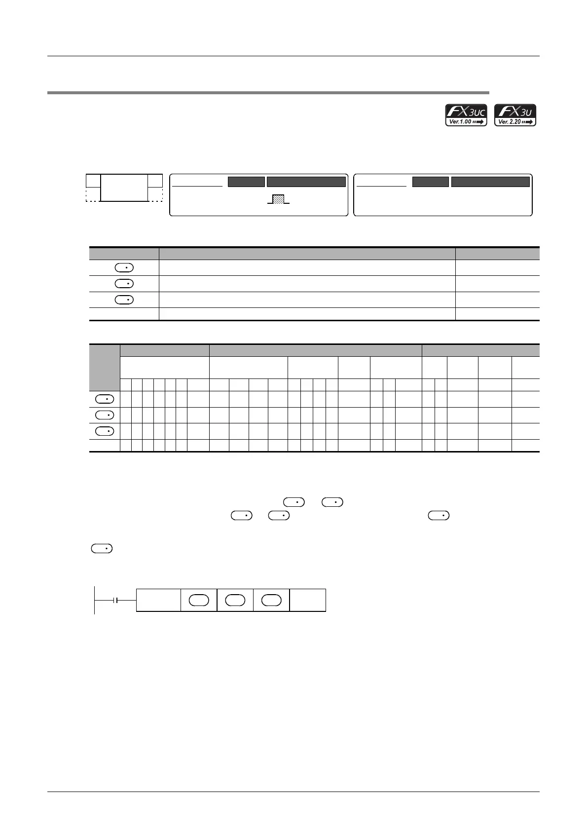
1. Instruction format
2. Set data
3. Applicable devices
S: "D.b" cannot be indexed with index registers (V and Z).
Explanation of function and operation
Four arrow switches are connected to the inputs to +3, a seven-segment display unit having the BCD
decoder is connected to the outputs to +7, and a numeric value is input to .
1. 16-bit operation (ARWS)
actually stores a 16-bit binary value ranging from 0 to 9999, but the value is expressed in the BCD format in the
explanation below for convenience.
When the command input is set to ON, the ARWS instruction executes the following operation.
Operand Type Description Data Type
Head bit device number to be input Bit
Word device number storing data converted into BCD 16-bit binary
Head bit device (Y) number connected to seven-segment display unit Bit
n Number of digits of seven-segment display unit [setting range: K0 to K3] 16-bit binary
Oper-
and
Type
Bit Devices Word Devices Others
System User Digit Specification System User
Special
Unit
Index
Con-
stant
Real
Number
Charac-
ter String
Pointer
XYMTCSD
.b KnX KnY KnM KnS T C D R
U\G
V Z Modify K H E "
"P
333 3 S 3
33333333
3 3
n 33
FNC 75
ARWS
ARWS
16-bit Instruction
9 steps
Mnemonic Operation Condition
Continuous
Operation
−
32-bit Instruction
Mnemonic Operation Condition
S
D
1
D
2
S
D
1
D
2
S
S
D
2
D
2
D
1
D
1
Command
input
FNC 75
ARWS
n
D
1
S
D
2

 Loading...


