GENERAL DESCRIPTION
FOUR-WHEEL ANTI-LOCK BRAKE SYSTEM (4ABS)
35B-3
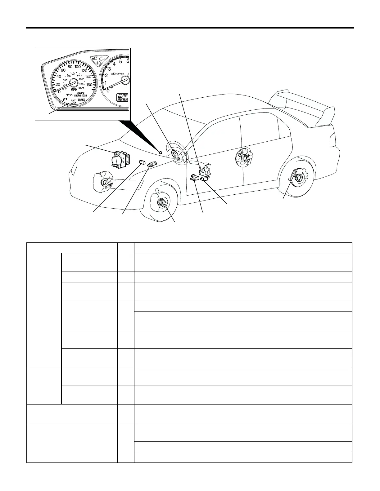
CONSTRUCTION DIAGRAM
10067AU
AC211546
AC209828
AB
1
1
3
5
2
4
6
9
7, 10
8
NAME OF PART NO. OUTLINE OF FUNCTION
Sensor ABS sensor 1 Sends alternating current signals at frequencies which are proportional
to the rotation speeds of each wheel to the ABS-ECU.
Lateral G-sensor 2 Sends data on vehicle’s rate of lateral acceleration to the ABS-ECU.
Longitudinal G-
sensor
3 Sends data on vehicle’s rate of longitudinal acceleration to the ABS-
ECU.
Steering angular
velocity sensor
4 Sends data on steering wheel angle to the ABS-ECU.
Indicates the ABS-ECU when steering wheel is in straight-ahead
position.
Stoplight switch 5 Sends a signal to the ABS-ECU to indicate whether the brake pedal is
depressed or not.
Parking brake
switch
6 Sends a signal to the ABS-ECU to indicate whether the parking brake
lever is pulled or not.
Actuator Hydraulic unit 7 Drives the solenoid valves according to signals from the ABS-ECU in
order to control the brake hydraulic pressure for each wheel.
ABS warning
light
8 Illuminates in response to signals from the ABS-ECU when a problem
develops in the system.
Data link connector 9 Outputs the diagnostic trouble codes and allows communication with
the scan tool.
Brake modulator (ABS-ECU) 10 Controls actuators (described above) based on the signals coming from
each sensor.
Controls the self-diagnosis and fail-safe functions.
Controls the diagnostic function (scan tool compatible).

 Loading...