5 - 2 5 - 2
MELSEC-A
5 PROGRAMMING
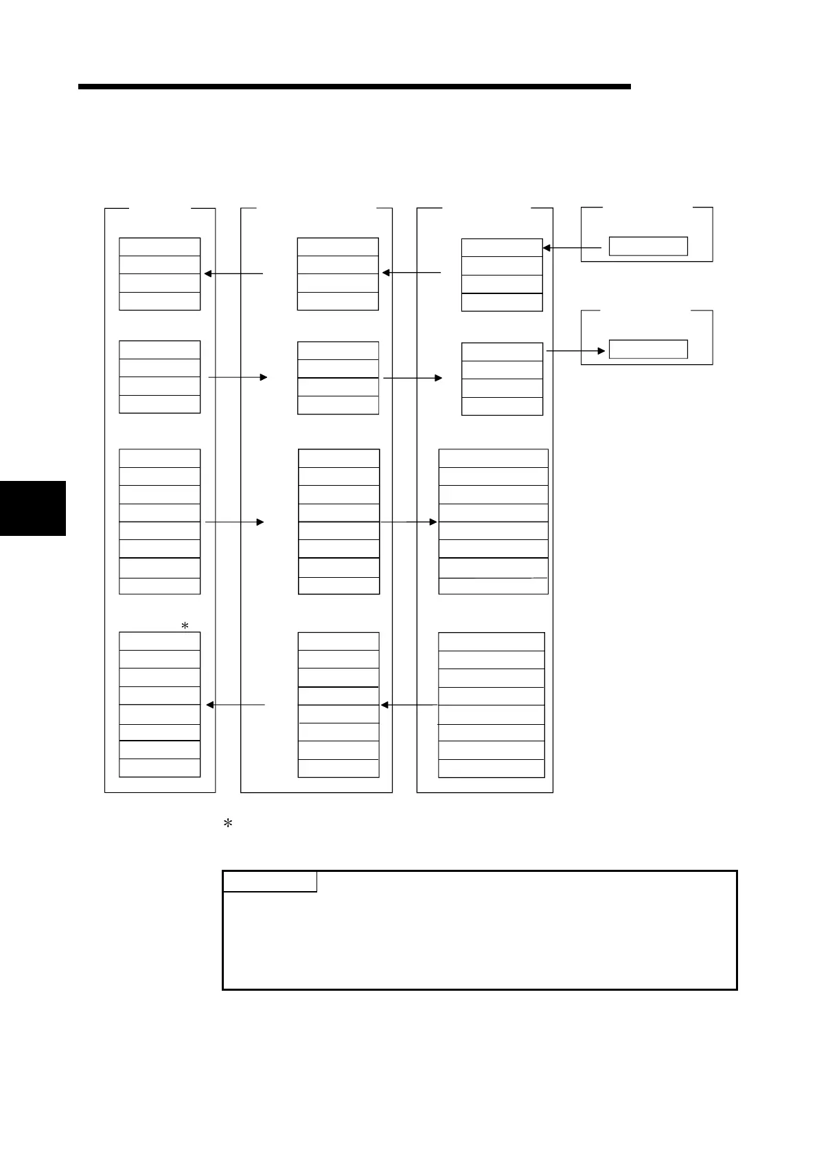
(2) Relation between PLC CPU, CC-Link master station, AJ65SBT-
CLB and CC-Link/LT remote I/O stations
Y408
to
Y40F
Y400 to Y40F
RWw3 Use prohibited
RX00 to RX0F
RX10 to RX1F
RX20 to RX2F
RX30 to RX3F
Remote input (RX)
RY00 to RY0F
RY10 to RY1F
RY20 to RY2F
RY30 to RY3F
RWw0 Last station number
Data link stop/
restart instructions
System
area
Remote register (RWw)
RWw1
Error status flag
clear
RWw2
RWw4 Use prohibited
RWw5 Use prohibited
RWw6 Use prohibited
RWw7 Use prohibited
RWr0
Remote register (RWr)
RWr1
RWr2
RWr4 Setting data
RWr5 Use prohibited
RWr6 Use prohibited
RWr7 Use prohibited
Remote I/O error
data
RWr3
Data of remote
station connection
System
area
X400 to X40F
X410 to X41F
X420 to X42F
X430 to X43F
Device X
Y410 to Y41F
Y420 to Y42F
Y430 to Y43F
Device Y
D200
D201
D202
D203
Device D
D204
D205
D206
D207
D300
D301
D302
D303
Device D
D304
D305
D306
D307
PLC CPU
161
H
RX00 to RX0F
RX10 to RX1F
RX20 to RX2F
RX30 to RX3F
Remote input (RX)
RY00
to
RY0F
RY10
to
RY1F
RY20 to RY2F
RY30 to RY3F
Remote register (RWw)
CC-Link master station
Remote output (RY)
Remote register (RWr)
RWr0
RWr1
RWr2
RWr3
RWr4
RWr5
RWr6
RWr7
E0
H
Address
E1
H
E2
H
E3
H
160
H
Address
162
H
163
H
1E0
H
1E1
H
1E2
H
1E3
H
1E4
H
1E5
H
1E6
H
1E7
H
2E0
H
2E1
H
2E2
H
2E3
H
2E4
H
2E5
H
2E6
H
2E7
H
X400
to
X407
Input
CL2X8-D1C3V
(Station No. 1)
Output
CL2Y8-TP1C2V
(Station No. 3)
Remote output (RY)
AJ65SBT-CLB
RWw0
RWw1
RWw2
RWw3
RWw4
RWw5
RWw6
RWw7
Data of
faulty station
Data of
operating statuses
In the program example created with the RRPA instruction (auto refresh parameter
setting) on the ACPU/QCPU (A mode), RWr0 - RWr7 are assigned to D456 to D463.
POINT
Depending on the CPU module, the devices used in the program examples of this
chapter may be unusable. For the valid ranges of the devices, refer to the users'
manual of the CPU module.
For example, when the A1SCPU is used, devices of X100, Y100 and later cannot
be used. Use the devices such as B and M.
5

 Loading...


