PROGRAM
MI
NG
I
[Sequence instruction description
I
Contact instructions
Operation start, series connection, parallel connection
(LD, LDI, AND, ANI, OR,
ORI)
Device number
___
I
I
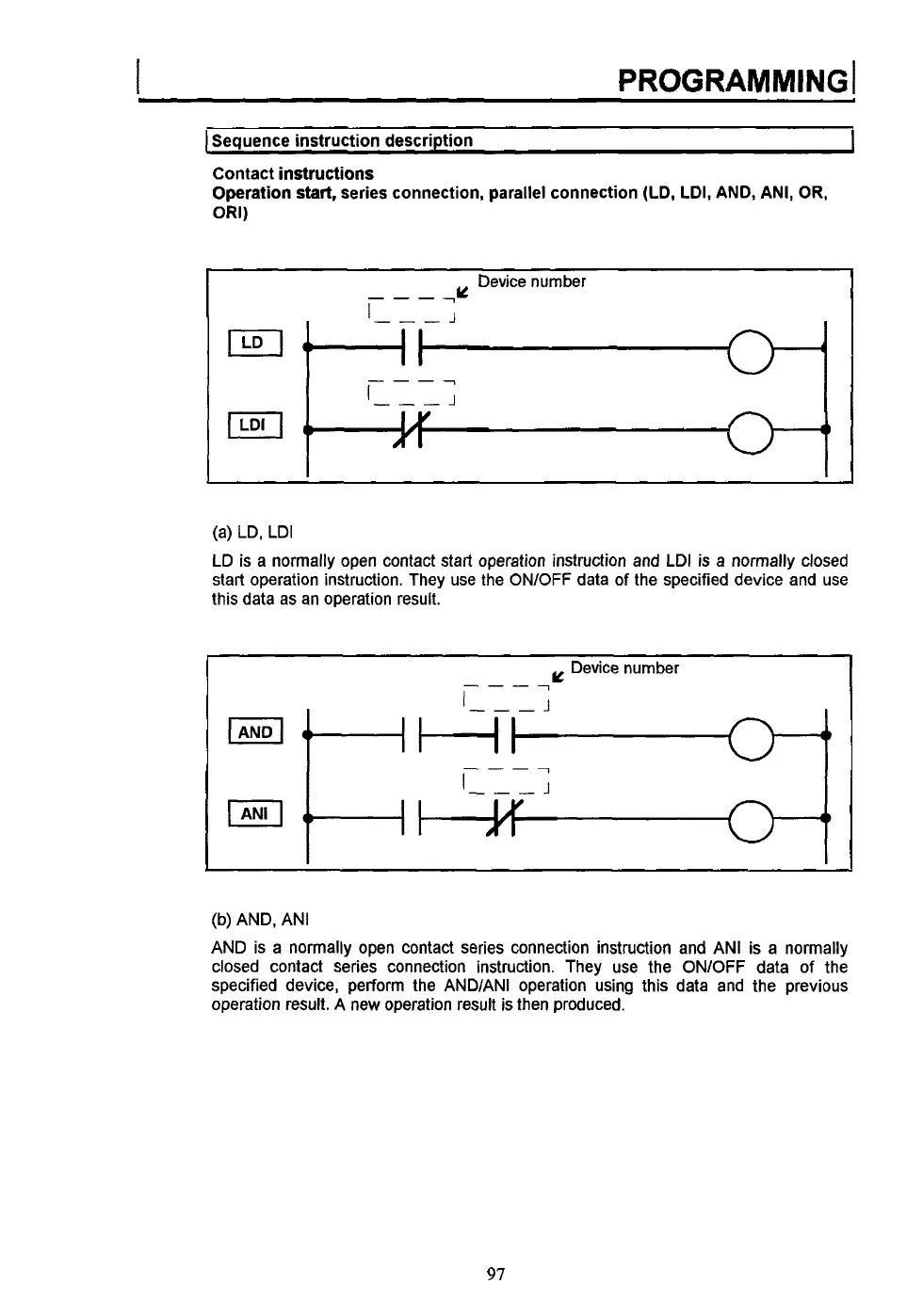
(a) LD, LDI
LD is a normally open contact start operation instruction and LDI is a normally closed
start operation instruction. They use the ON/OFF data
of
the specified device and use
this data as an operation result.
(b) AND, ANI
AND is a normally open contact series connection instruction and ANI is a normally
closed contact series connection instruction. They use the ONlOFF data of the
specified device, perform the AND/ANI operation using this data and the previous
operation result. A new operation result is then produced.
97
 Loading...