EasyManua.ls Logo

Mitsubishi MELSEC A1S62P User Manual

Mitsubishi MELSEC A1S62P
149 pages
To Next Page IconTo Next Page
To Previous Page IconTo Previous Page
Page #67 background imageLoading...
Page #67 background image
!
I
Timing chart
I
ON
x5
OFF-
ON
T2
contacts
OFF
I
Counter
c
I
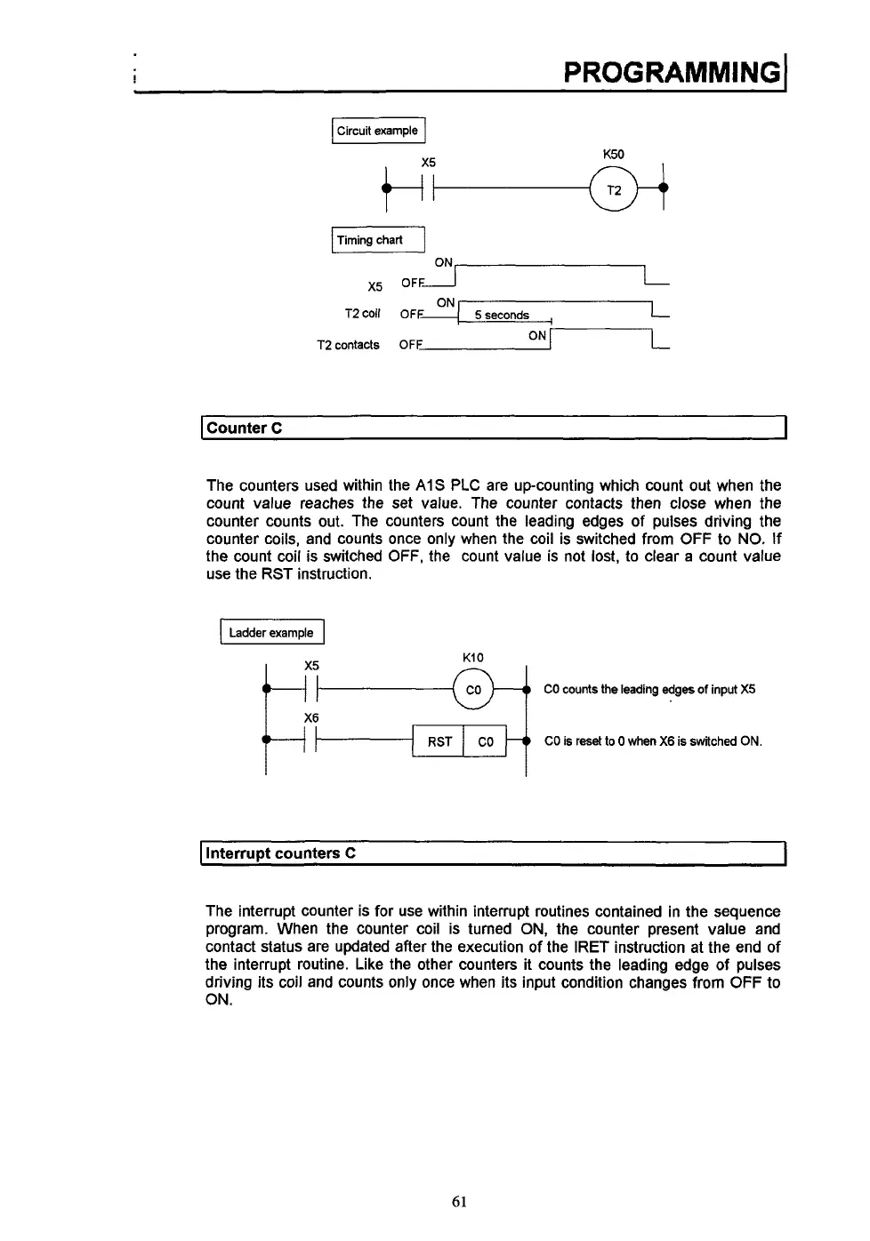
The counters used within the
AIS
PLC are up-counting which count
out
when the
count value reaches the set value. The counter contacts then close when the
counter counts out. The counters count the leading edges of pulses driving the
counter coils, and counts once only when the coil is switched from
OFF
to
NO,
If
the count coil
is
switched
OFF,
the count value is not lost,
to
clear
a
count value
use the RST instruction.
I
Ladderexample
I
I
I
CO
counts the leading edges
of
input
X5
CO
is
reset
to
0
when
X6
is switched
ON.
I
Interrupt counters
c
I
The interrupt counter is for use within interrupt routines contained in the sequence
program. When the counter coil
is
turned
ON,
the counter present value and
contact status are updated afler the execution of the IRET instruction at the end
of
the interrupt routine. Like the other counters
it
counts the leading edge
of
pulses
driving its coil and counts only once when its input condition changes from
OFF
to
ON.
61

Table of Contents

Question and Answer IconNeed help?

Do you have a question about the Mitsubishi MELSEC A1S62P and is the answer not in the manual?

Mitsubishi MELSEC A1S62P Specifications

General IconGeneral
CategoryController
SeriesMELSEC A
ModelA1S62P
Input VoltageAC 100-240V
Input Frequency50/60 Hz
Input TypeDigital
Output TypeRelay
Communication InterfaceRS-232
MountingDIN rail
Operating Temperature0 to 55 °C
TypeProgrammable Logic Controller (PLC)
Output Current0.5A
Power Supply100-240V AC
Storage Temperature-25°C to 75°C
Humidity5% to 95% (non-condensing)

Summary

Chapter 1: Overview of the A1S PLC

What is the A1S?

Introduction to the Mitsubishi A1S PLC as a low-cost, high-performance controller.

How Does It Work?

Explanation of the sequential control program execution and CPU module operation.

Chapter 2: A1S Module Descriptions

Central processing unit (CPU Module)

Details the CPU module, its functions, and specifications.

CPU Base Units

Describes CPU base units for mounting CPU, power supply, and I/O modules.

Special function modules

Explains intelligent I/O modules for specific applications like control, linking, and networking.

Power supply modules

Explains power supply modules providing 5 VDC for CPU and I/O modules.

Input modules

Describes input modules for interfacing with external input devices.

Model No. A1SX10

Details the A1SX10 input module with 16 x 110 VAC inputs and terminal block wiring.

Model No. A1SX20

Details the A1SX20 input module with 16 x 240 VAC inputs and terminal block wiring.

Model No. A1SX30

Details the A1SX30 input module with 16 x 24 VAC/VDC inputs and terminal block wiring.

Output modules

Describes output modules for interfacing with external output devices.

Special function modules

Explains intelligent I/O modules for specific applications like control, linking, and networking.

Chapter 3: System Selection and Configuration

System selection

Guide to selecting the appropriate AIS PLC system components based on application needs.

Step 1: Input module selection

A flowchart to help select the correct input module based on specifications.

Step 2: Output module selection

A flowchart to help select the correct output module based on specifications.

Step 3: Special function module selection

A flowchart to guide the selection of special function modules based on application requirements.

Step 4: Power supply module selection

A flowchart for selecting the appropriate power supply module based on voltage and output needs.

Step 5: Base unit selection

A flowchart for selecting the base unit based on the number of required I/O slots.

System configuration

Instructions on configuring the system and assigning I/O numbers to selected modules.

Chapter 4: Installation

Base unit mounting instructions

Provides guidelines for mounting CPU and extension base units, including clearance.

Installation and removal of AIS modules

Explains how to install and remove AIS modules from the base unit.

Removing a module from the base unit

Step-by-step guide for removing a module from the base unit.

Chapter 5: Wiring

Wiring instructions for the power supply module

Provides wiring guidelines for power supply modules, including transformer usage.

Wiring of I/O equipment

Wiring instructions for equipment connected to input and output modules.

Grounding

Guidelines for proper grounding of the PLC system.

Chapter 6: Programming

Description of internal devices

Explains internal devices used in sequence programs like relays, timers, and counters.

Instructions

Classifies and introduces instructions into three groups: sequence, basic, application.

Output instructions

Explains output instructions like OUT for bit devices, timers, and counters.

Bit device set, reset (SET, RST)

Explains SET and RST instructions for controlling bit devices.

Edge-triggered differential output (PLS, PLF)

Explains PLS and PLF instructions for pulse output generation.

Master control instructions

Explains master control instructions MC and MCR for circuit switching.

Basic instruction descriptions

Introduces basic instructions for handling numeric data.

Comparison operation instructions

Explains instructions for numerical magnitude comparisons.

Arithmetic operation instructions

Explains instructions for performing addition, subtraction, multiplication, division.

Data transfer instructions

Explains instructions for data transfer and interchange.

Application instruction descriptions

Classifies and introduces application instructions for special processing.

Related product manuals