:PROGRAMMING
I
Pointer
P
I
The pointer
(P)
indicates the jump destination for the branch instructions
CJ, SCJ,
CALL,
JMP,
and the pointer number attached
to
the beginning
of
the jump
destination is referred
to
as a label. The same label cannot be used multiple times,
in the case
of
multiple use an error
will
occur. The label
255
always indicates the
END
instruction
of
the sequence program and cannot be used as a label.
I
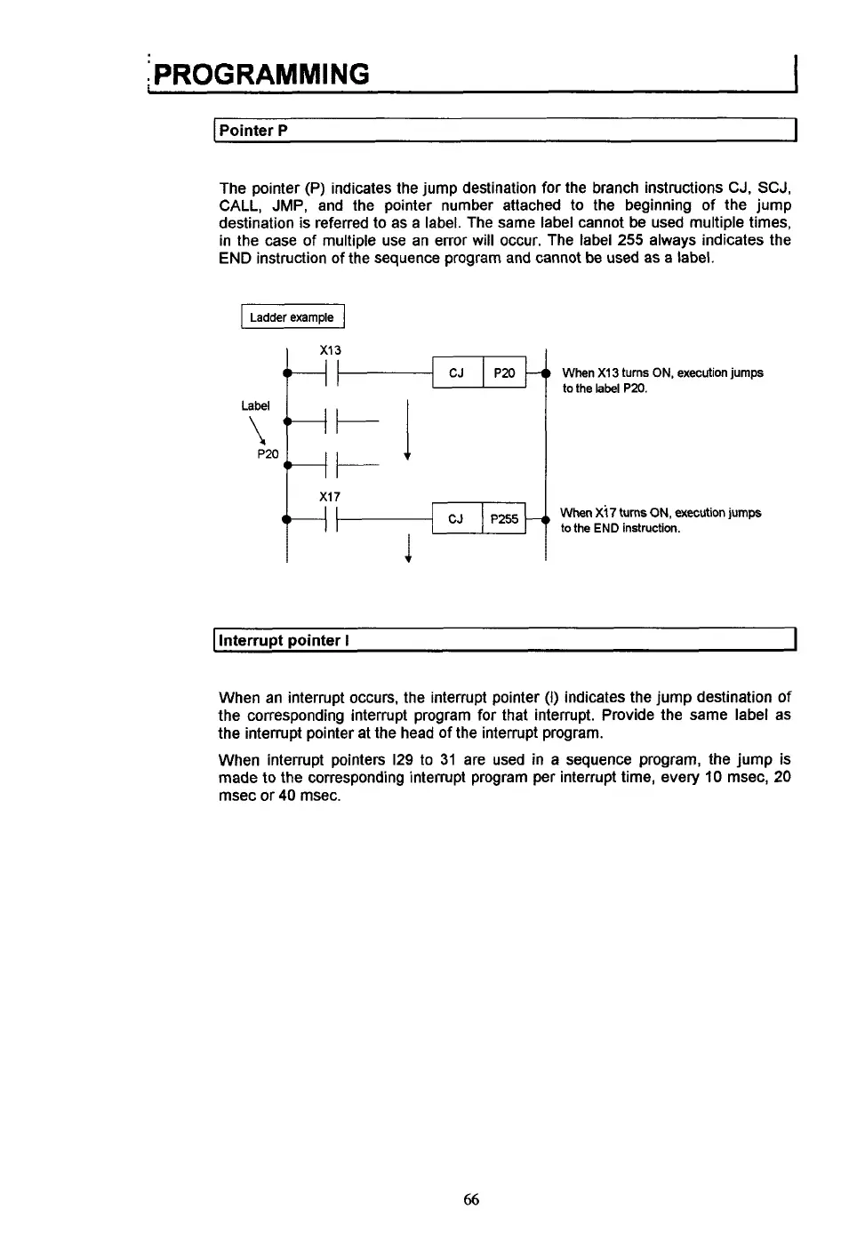
Ladderexample
1
When
XI3
turns
ON,
execution jumps
to the
label
P20.
When
Xi7
turns
ON,
executicn
jumps
to the
END
instruction.
Interrupt pointer
I
I
When an interrupt occurs, the interrupt pointer
(I)
indicates the jump destination
of
the corresponding interrupt program for that interrupt. Provide the same label as
the interrupt pointer at the head of the interrupt program.
When interrupt pointers
129
to
31
are used in
a
sequence program, the jump is
made
to
the corresponding interrupt program per interrupt time, every
10
msec,
20
msec or
40
msec.
66
 Loading...