EasyManua.ls Logo

Mitsubishi MELSEC A1S62P User Manual

Mitsubishi MELSEC A1S62P
149 pages
To Next Page IconTo Next Page
To Previous Page IconTo Previous Page
Page #76 background imageLoading...
Page #76 background image
i
PROGRAMMING
I
I
Soecial reaisters
D
I
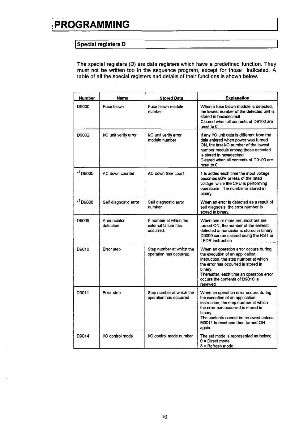
The special registers
(D)
are data registers which have a predefined function. They
must not be written
too
in
the
sequence program, except for those indicated.
A
table
of
all
the
special registers and details
of
their functions is shown below.
Number
D9000
D9002
D9005
*'D9008
D9009
D9010
D9011
D9014
Name
Fuse blown
I/O unit verify error
AC down counter
Self
diagnostic error
Annunciator
detection
Error step
Error step
I/O
control mode
Stored Data
Fuse blown module
number
110
unit verify error
module number
AC down time count
Self diagnostic error
number
F
number at which the
external failure has
occurred.
Step number at which the
operation has occurred.
Step number at which the
operation has occurred.
110
control mode number
Explanation
When
a
fuse blown module is detected,
the
lowest
number
of
the detected unit is
stored in hexadecimal.
Cleared when all contents of D91W are
reset
to
0.
If any
110
unit data is different from the
data entered when power was turned
ON, the first
110
number
of
the lowest
number module among those detected
is stored in hexadecimal.
Cleared when all contents of D91W are
reset
to
0.
1 is added each time the input voltage
becomes
80%
or
less
of the rated
voltage while the
CPU
is performing
operations. The number is stored in
binary.
When an error is detected as a result of
self diagnosis, the error number is
stored in binarv.
When one or more annunciators are
turned
ON,
the number of the earliest
detected annunciator is stored in binary.
D9009 can be cleared using the RST or
LEDR instruction.
When an operation error occurs during
the execution of an application
instruction, the step number at which
the error has occurred
is
stored in
binary.
Thereafter, each time an operation error
occurs the contents
of
D9010 is
renewed
When an operation error occurs during
the execution of an application
instruction, the step number at which
the error has occurred is stored in
binary.
The contents cannot be renewed unless
M9011 is reset and then turned
ON
again.
The set mode is represented as below;
0
=
Direct mode
3
=
Refresh mode
70

Table of Contents

Question and Answer IconNeed help?

Do you have a question about the Mitsubishi MELSEC A1S62P and is the answer not in the manual?

Mitsubishi MELSEC A1S62P Specifications

General IconGeneral
CategoryController
SeriesMELSEC A
ModelA1S62P
Input VoltageAC 100-240V
Input Frequency50/60 Hz
Input TypeDigital
Output TypeRelay
Communication InterfaceRS-232
MountingDIN rail
Operating Temperature0 to 55 °C
TypeProgrammable Logic Controller (PLC)
Output Current0.5A
Power Supply100-240V AC
Storage Temperature-25°C to 75°C
Humidity5% to 95% (non-condensing)

Summary

Chapter 1: Overview of the A1S PLC

What is the A1S?

Introduction to the Mitsubishi A1S PLC as a low-cost, high-performance controller.

How Does It Work?

Explanation of the sequential control program execution and CPU module operation.

Chapter 2: A1S Module Descriptions

Central processing unit (CPU Module)

Details the CPU module, its functions, and specifications.

CPU Base Units

Describes CPU base units for mounting CPU, power supply, and I/O modules.

Special function modules

Explains intelligent I/O modules for specific applications like control, linking, and networking.

Power supply modules

Explains power supply modules providing 5 VDC for CPU and I/O modules.

Input modules

Describes input modules for interfacing with external input devices.

Model No. A1SX10

Details the A1SX10 input module with 16 x 110 VAC inputs and terminal block wiring.

Model No. A1SX20

Details the A1SX20 input module with 16 x 240 VAC inputs and terminal block wiring.

Model No. A1SX30

Details the A1SX30 input module with 16 x 24 VAC/VDC inputs and terminal block wiring.

Output modules

Describes output modules for interfacing with external output devices.

Special function modules

Explains intelligent I/O modules for specific applications like control, linking, and networking.

Chapter 3: System Selection and Configuration

System selection

Guide to selecting the appropriate AIS PLC system components based on application needs.

Step 1: Input module selection

A flowchart to help select the correct input module based on specifications.

Step 2: Output module selection

A flowchart to help select the correct output module based on specifications.

Step 3: Special function module selection

A flowchart to guide the selection of special function modules based on application requirements.

Step 4: Power supply module selection

A flowchart for selecting the appropriate power supply module based on voltage and output needs.

Step 5: Base unit selection

A flowchart for selecting the base unit based on the number of required I/O slots.

System configuration

Instructions on configuring the system and assigning I/O numbers to selected modules.

Chapter 4: Installation

Base unit mounting instructions

Provides guidelines for mounting CPU and extension base units, including clearance.

Installation and removal of AIS modules

Explains how to install and remove AIS modules from the base unit.

Removing a module from the base unit

Step-by-step guide for removing a module from the base unit.

Chapter 5: Wiring

Wiring instructions for the power supply module

Provides wiring guidelines for power supply modules, including transformer usage.

Wiring of I/O equipment

Wiring instructions for equipment connected to input and output modules.

Grounding

Guidelines for proper grounding of the PLC system.

Chapter 6: Programming

Description of internal devices

Explains internal devices used in sequence programs like relays, timers, and counters.

Instructions

Classifies and introduces instructions into three groups: sequence, basic, application.

Output instructions

Explains output instructions like OUT for bit devices, timers, and counters.

Bit device set, reset (SET, RST)

Explains SET and RST instructions for controlling bit devices.

Edge-triggered differential output (PLS, PLF)

Explains PLS and PLF instructions for pulse output generation.

Master control instructions

Explains master control instructions MC and MCR for circuit switching.

Basic instruction descriptions

Introduces basic instructions for handling numeric data.

Comparison operation instructions

Explains instructions for numerical magnitude comparisons.

Arithmetic operation instructions

Explains instructions for performing addition, subtraction, multiplication, division.

Data transfer instructions

Explains instructions for data transfer and interchange.

Application instruction descriptions

Classifies and introduces application instructions for special processing.

Related product manuals