12
TROUBLESHOOTING
12.2 Troubleshooting Flowchart
12.2.7 Flowchart for when the "ERR." LED turns on or flashes
12 - 11
9
EMC AND LOW
VOLTAGE
DIRECTIVES
10
LOADING AND
INSTALLATION
11
MAINTENANCE AND
INSPECTION
12
TROUBLESHOOTING APPENDICES INDEX
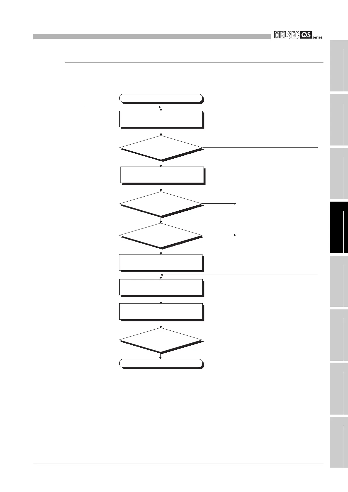
12.2.7 Flowchart for when the "ERR." LED turns on or flashes
The following shows the flowchart for when the "ERR." LED of the CPU module turns on or
flashes at of the programmable controller power-on, at operation start or during operation.
(1) Flowchart for when "MODULE
VERIFY ERROR" occurs
(2) Flowchart for when
"CONTROL-BUS ERROR"
occurs
The "ERR." LED is on/flashing.
Completed
Confirm details of the error by GX
Developer. (Perform PLC diagnostics.)
NO
Can PLC diagnostics be
performed?
YES
Set the RUN/STOP/RESET switch
to STOP.
Is "UNIT MODULE ERROR"
occurring?
NO
Is "CONTROL-BUS
ERROR" occurring?
Modify error details according to
PLC diagnostics.
NO
Reset the CPU module by the
RUN/STOP/RESET switch.
Set the RUN/STOP/RESET switch
to RUN.
Does the "ERR."
LED turn off?
YES
NO
YES
YES

 Loading...

