2
SYSTEM CONFIGURATION
2.1 System Configuration
2.1.1 Precautions for system configuration
2 - 3
1
OVERVIEW
2
SYSTEM
CONFIGURATION
3
GENERAL
SPECIFICATIONS
4
CPU MODULE
5
POWER SUPPLY
MODULE
6
BASE UNIT
7
BATTERY
8
CPU MODULE START-
UP PROCEDURES
2.1.1 Precautions for system configuration
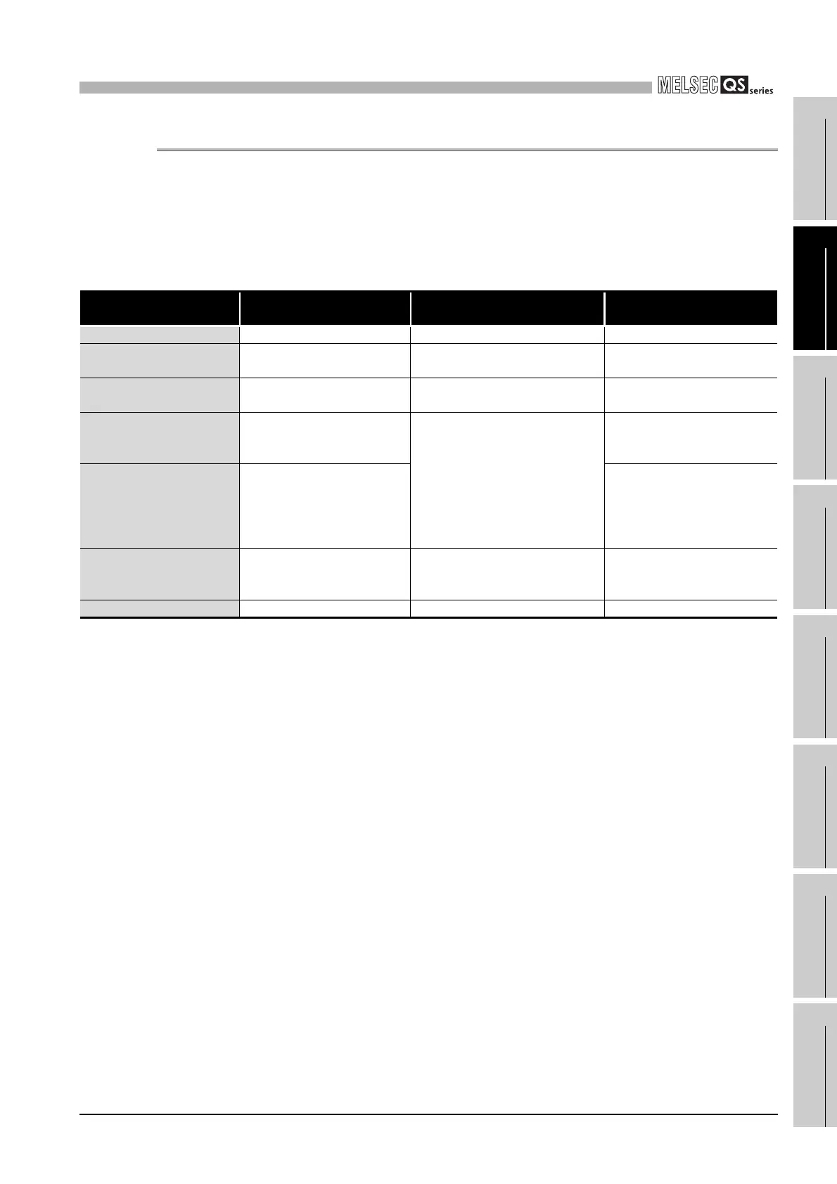
(1) Modules mountable on the main base unit
Table2.2 lists the modules that can be mounted on the main base unit.
The number of mounted modules and functions are restricted depending on the
module type.
Table2.2 Modules mountable on the main base unit
Module Model
Number of modules
mounted in one system
Remarks
CPU module • QS001CPU Only one ---
Power supply module
• QS061P-A1
• QS061P-A2
Only one (only one of the module
models)
---
CC-Link Safety master
module
• QS0J61BT12 Up to two ---
CC-Link IE controller network
module
• QJ71GP21-SX
• QJ71GP21S-SX
Only one (only one of the models
among CC-Link IE controller network
modules and MELSECNET/H
modules)
• The first five digits of the serial
number are “10041” or higher
• Function version D or later
MELSECNET/H module
• QJ71LP21-25
• QJ71LP21S-25
• QJ71LP21G
• QJ71LP21GE
• QJ71BR11
---
Ethernet module
• QJ71E71-B2
• QJ71E71-B5
• QJ71E71-B100
Only one (only one of the module
models)
---
Blank cover • QG60 Up to four ---

 Loading...

