BALANCER CHAIN <4B12>
ENGINE OVERHAUL
11B-50
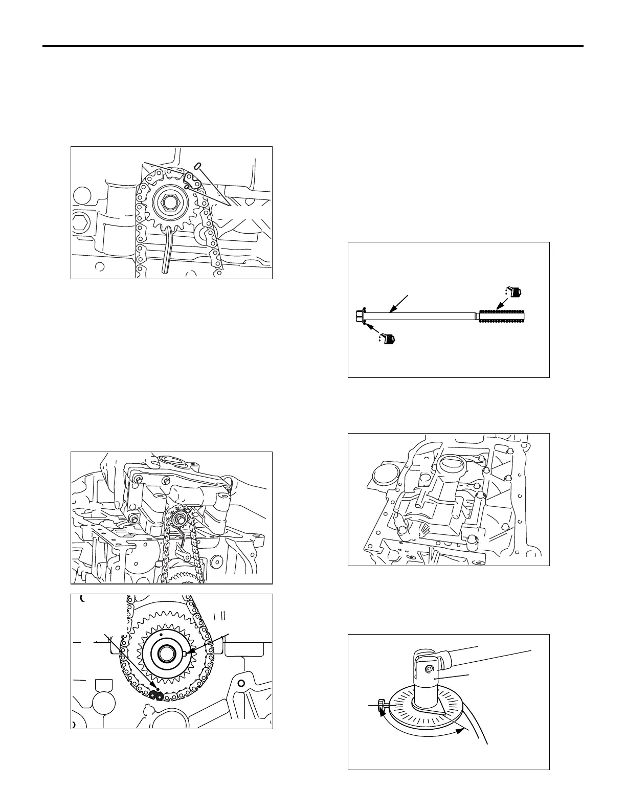
1. Wipe the dirt on the crankshaft sprocket and the
crankshaft using a rag, and then remove the
grease from the portion shown in the illustration.
NOTE: Remove grease to prevent a drop in the
coefficient of friction of the pressing portion
caused by adhesion of oil.
AK502753
AC
Timing mark
Balancer chain
link plate
(orange)
2. Align the timing mark of the balancer shaft module
sprocket with that of the balancer shaft module.
3. Insert a hexagonal bar wrench (3 mm) as
illustrated to prevent the balancer shaft module
sprocket from moving.
4. Loop the balancer chain, aligning its link plate
(orange) with the timing mark.
5. Install the crankshaft sprocket on the crankshaft.
NOTE: Do not push in the crankshaft sprocket to
the normal position. Push it in only up to the tip of
the crankshaft.
AK502754
AK503334
AC
Crankshaft
sprocket
timing mark
Key groove
6. While slanting the balancer shaft module, align
the link plate (blue) of another balancer chain with
the timing mark of the crankshaft sprocket to loop.
Gradually push in the crankshaft sprocket and fit it
into the key groove of the crankshaft. Then, install
the balancer shaft module on the ladder frame.
NOTE: Make sure that the balancer shaft module
is completely intimate contact with the ladder
frame.
NOTE: Make sure that the key groove of the
crankshaft is aligned with the contact surface of
the cylinder block and ladder frame as shown in
the illustration.
AK503386
AC
Balancer shaft
module bolt
7. Apply an appropriate and minimum amount of
engine oil to the screw thread of the balancer
shaft module bolt.
AK502804
1
2
3
4
AC
8. Tighten bolts to the specified torque of 20 N⋅m
according to the assembly order in the illustration,
retighten them to 44 N
⋅m, and then completely
loosen them.
AK503158
AC
135˚
MB991614

 Loading...