AK502749
90˚
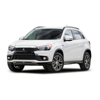
Paint mark
AC
Paint mark
PISTON AND CONNECTING ROD
ENGINE OVERHAUL
11B-58
6. Put a paint mark on the bolt head as illustrated.
7. Put a paint mark on the connecting rod at 90°
position in the tightening direction of the bolt with
reference to the paint mark position of the bolt.
CAUTION
• When the tightening angle is smaller than the
specified tightening angle, the appropriate
tightening capacity cannot be secured.
• When the tightening angle is larger than the
specified tightening angle, remove the bolt to
start from the beginning again according to
the procedure.
8. Tighten the bolt 90°, and make sure that the paint
mark of the connecting rod is aligned with that of
the bolt.
INSPECTION
M1113008502703
PISTON RINGS
AK502751
1. Check clearance between piston rings and ring
grooves. If the limit is exceeded, replace piston
rings or piston, or both.
Standard value:
No. 1 ring: 0.03 − 0.07 mm
No. 2 ring: 0.03 − 0.07 mm
Limit: 0.1 mm
AK503370
AG
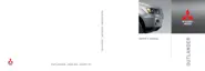
Press down ring
with piston
End gap
Piston ring
Front mark
2. Put piston rings into the cylinder bore, press them
against the piston top face, and push them in.
After achieving squareness, measure the end gap
with a thickness gauge. If the end gap is
excessive, replace piston rings.
Standard value:
No. 1 ring: 0.15 − 0.28 mm <4B11>
No. 1 ring: 0.15 − 0.25 mm <4B12>
No. 2 ring: 0.30 − 0.45 mm <4B11>
No. 2 ring: 0.25 − 0.40 mm <4B12>
Oil ring: 0.10 − 0.35 mm
Limit:
No. 1 ring: 0.8 mm
No. 2 ring: 0.8 mm
Oil ring: 1.0 mm
CRANKSHAFT PIN OIL CLEARANCE
(PLASTIGAGE METHOD)
1. Wipe oil off the crankshaft pin and connecting rod
bearing.
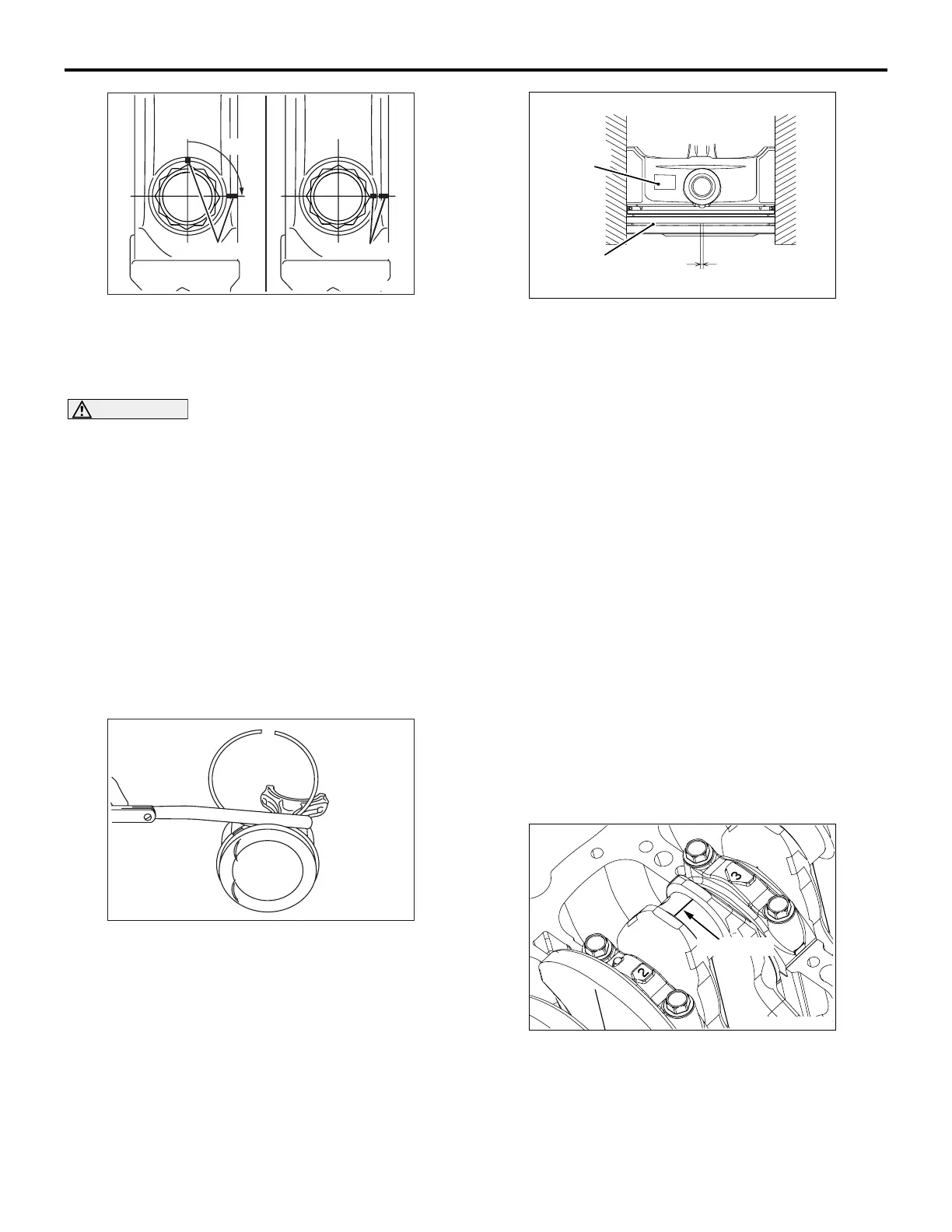
2. Place a Plastigage in length equal to the bearing
width on the pin shaft straight in alignment with
the shaft centre.
AK503373
AC
Plastigage
3. Carefully install the connecting rod cap and
tighten bolts to the specified torque of 5.0 N
⋅m →
20 N
⋅m → +90°.
4. Remove bolts and gently remove the connecting
rod cap.

 Loading...