8-32 Maintenance: VHF Troubleshooting Charts
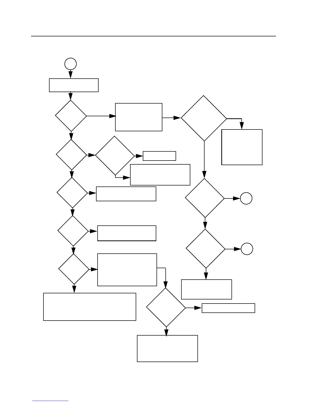
8.12.6 Troubleshooting Flow Chart for Receiver for models with PCB 8486473Z04
(Sheet 2 of 2)
IF Signal at
L3200?
No
RF Signal at
T3301?
RF Signal at
R3313?
No
RF Signal at
C3306?
No
RF Signal at
C3302?
No or
Check harmonic filter L3531 & L3532,
C3532 and ant. switches D3521, D3551,
L3551, R3551, C3551, C3552, L3552
Check filter between
C3302 & C3306; pro-
gram filter to schematic
test freq and check
varactor voltages.
Inject RF into J3501
Are varactor
voltages OK?
No
Yes
Check RF amp (Q3302)
Stage.
Check filter between
C3313 & T3301.
Yes
Check T3301, T3302,
CR3301, R3321, R3322,
R3323
Yes
1st LO O/P
OK?
Locked?
Yes
Check FGU
Yes
Trace IF signal
from L3200 to
Q3200. Check for
bad XTAL filter.
No
Yes
Q3200 collec-
tor OK?
IF signal
present?
Before replacing
U3220, check
U3220 volt-
ages; trace IF
signal path.
Yes
Check for 2.9
VDC
Is R5
present?
Check Q3721,
U3701 (pin 48) volt-
ages and U247
No
No
No
Check U404 voltage and if
U404 can be selected by
MCU before replacing
U404.
Check varactor filter.
No
Yes
Yes
Yes
A
A
B
weak RF

 Loading...


