3-2 Keypad: Controller Board
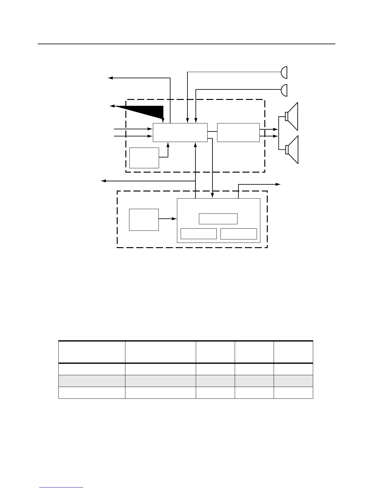
Figure 3-2. Controller Block Diagram
3.1.1 MCU Digital
The digital portion of the controller consists of a microcontroller and associated EEPROM, RAM, and
ROM memories. Combinations of different size RAM and ROM are available to support various
application software. RAM supports 8KB and 32KB sizes. ROM supports 128KB, 256KB, and 512KB
sizes. Tabl e 3- 1 lists the ROM, RAM and EEPROM requirements for different radios.
3.1.2 Real Time Clock
Radios with displays support a real time clock (RTC) module for purposes of message time stamping
and time keeping. The RTC module resides in the microcontroller. The clock uses a back-up lithium-
ion battery for operating power when the primary battery is removed.
Table 3-1. Radio Memory Requirements
PROTOCOL FEATURE LEVEL ROM (KB)
EXT RAM
(KB)
EEPROM
(KB)
AA,DU 2 or 3 128 - 8
AA,DU 6 128 - 16
CK, GB, GE, FC - 512 32 16
External
Microphone
Internal
Microphone
External
Speaker
Internal
Speaker
SCI to Side
Connector
Audio/Signalling
To Synthesizer
Mod Out
16.8 / 17.0 MHz
Reference Clock
from Synthesizer
Recovered Audio
Squelch
SPI
MCU Digital
RAM
EEPROM
ROM
Microcontroller
ASFIC
3.3V
Regulator
(Vdda)
3.3V
Regulator
(Vddd)
Audio Power
Amplifier/Filter
CLK
To RF Board

 Loading...


