7-20 Low Band, 800 MHz, PassPort & 900 MHz Theory of Operation: 900 MHz Receiver
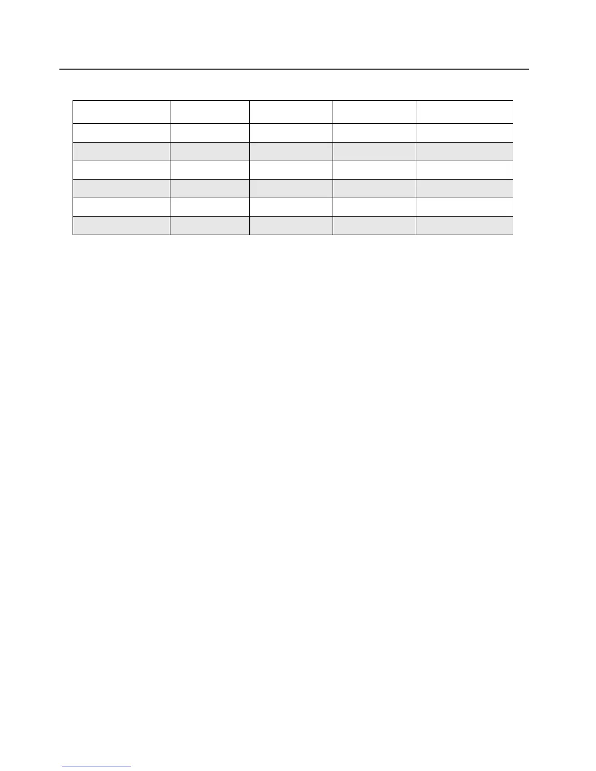
*RX1:receive voice with carrier squelch, PL or DPL (Flutter Fighter can be on or off).
**RX2:refers to receive mode with all other data HST/MDC/DTMF (Flutter Fighter must be off).
7.11.3.1 Receive Path for Radios with Hear Clear
The audio signal enters Hear Clear controller from DEMOD_OUT signal on DISC. The detected
audio “DISC” enters the Hear Clear Flutter Fighter through C857 and C859. C857 connects the
signal to FF IN (U851-E4). C859 is a beginning of a noise sampling circuit consisting of components
– C859, R853, C860, R854, C861, R855 and C862; and Hear Clear Ports Ref, Noise Filter In, and
Noise Filter Out, Noise Hold.
After exiting Hear Clear at the “FF OUT” (U851-F4), the signal enters ASFIC at DISC (U404-2).
Within the ASFIC, the signal passes through a low pass filter and high pass filter limiting the audio
bandwidth to 300 Hz-3 kHz. It then goes through de-emphasis and exits the ASFIC at AUDIO (U404-
41). The audio is then routed to the Audio PA in the same manner as the standard receive audio.
The purpose of the Flutter Fighter is to sample the amount of Noise in the receive audio between 10-
20 kHz using the Noise Filter (U851-B5), Noise Filter Out (U851-C6), and Noise Hold (U851-D5). In
addition, it monitors the rate of change of RSSI (Receive Signal Strength In) (U303-1). The detected
audio DISC enters into the Hear Clear IC at “FF IN” (U851-E4). The circuit then reduces the amount
of popping Noise associated with fading. The improved audio exits the IC at “FF OUT” (U851-F4).
7.11.3.2 Hear Clear Routing of Data/Signaling
While receiving, sub-audible signals PL/DPL go through the Flutter Fighter along with the audio, and
is unaffected by the Flutter Fighter operation. On entering the ASFIC, the sub-audible signaling is
separated from the voice and decoded.
While receiving other signals HST/MDC (not sub-audible), the Flutter Fighter is set to the “pass
through mode”. In this mode, the Flutter Fighter is routed from ”FF IN” to “FF OUT” without any
processing.
7.11.4 Automatic Gain Control Circuit
The automatic gain control circuit provides automatic gain reduction of both the low noise amplifier in
the receiver front end and the IF amplifier in the receiver backend. This action is necessary to
prevent overloading of the backend IF IC.
Table 7-2. Hear Clear Logic and IC Status
Name Ref. Des Set By RX1* RX2**
IC Enable U851-C4 SWB+ 1 1
Flutter Fighter Enable U851-E3 DACRX 1 0
LO Clamp Disable U851-A5 SWB+ 1 1
LO Clamp Disable U851-C2 GND 0 0
HCI Disable U851-B6 SWB+ 1 1
LO Clamp Disable U851-D1 GND 0 0

 Loading...


