2-22
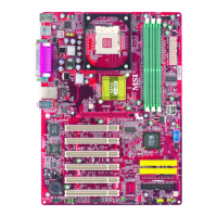
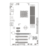
MS-7176 ATX Mainboard
Testing Base and Extended Memory
Testing base memory from 240K to 640K and extended
memory above 1MB using various patterns.
Assign Resources to all ISA.
Initializing Hard Drive Controller
This will initialize IDE drive and controller.
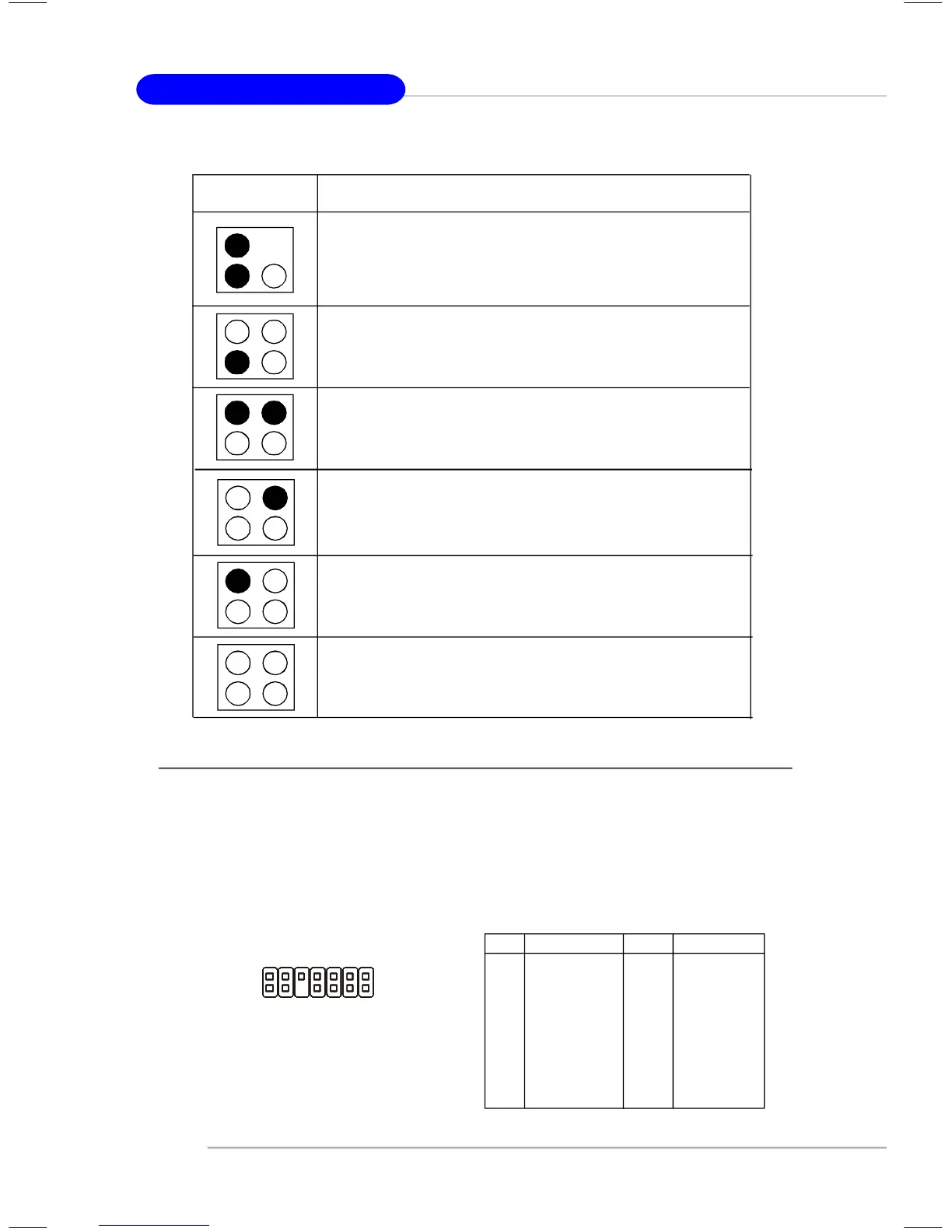
D-Bracket™ 2 Description
Initializing Floppy Drive Controller
This will initialize Floppy Drive and controller.
Boot Attempt
This will set low stack and boot via INT 19h.
Operating System Booting
JLPC1 Pin Definition
PIN SIGNAL PIN SIGNAL
1 LCLK 2 Key (no pin)
3 LRST# 4 VCC3
5 LAD0 6 FID0_LRST
7 LAD1 8 VCC5
9 LAD2 10 Key (no pin)
11 LAD3 12 GND
13 LFRAME# 14 GND
JLPC1
13
14
2
1
FWH/LPC Debugging Pin Header: JLPC1
The pin header is for internal debugging only.
 Loading...