MS-6421 Media Center
2-16
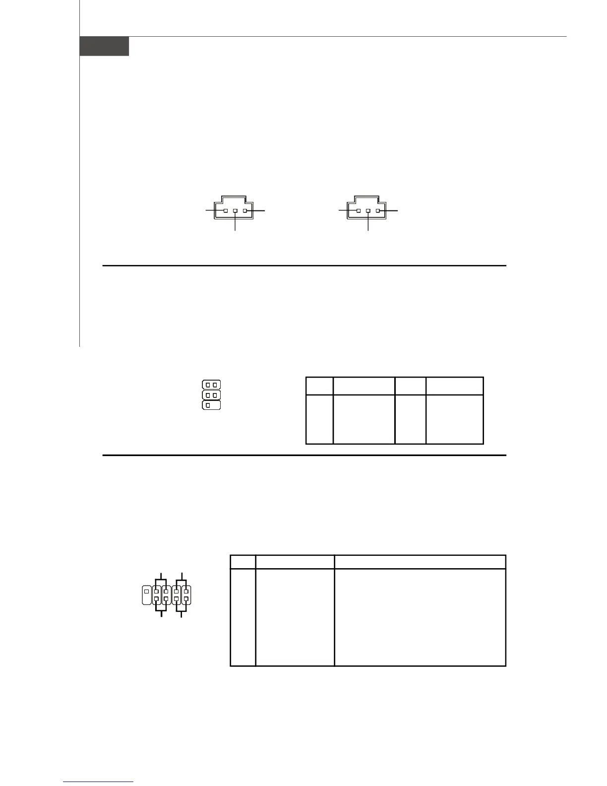
SPDIF-Out/In Connectors: JSPDO1 & JSPDI1 (SPDIF-In is Optional)
These connectors are used to connect SPDIF (Sony & Philips Digital Interconnect
Format) interface for digital audio transmission. The JSPDO1 is for SPDIF-Out and the
JSPDI1 is for SPDIF-In.
TV-Out Connector: JTV1 (Optional)
The mainboard optionally provides a TV-Out connector for you to attach a TV-Out
bracket that integrated HDTV-out. The TV-Out bracket offers two types of TV-Out
connectors: S-Video and RCA Composite connectors. Select the appropriate one to
connect to the standard television or the HDTV (High-Definition TeleVision) and it will be
able to display PC’s information.
Pin Description Pin Description
1 GND 2 COMP
3 Yout 4 GND
5 Cout
Pin Definition
JTV1
1
5
2
6
JSPDI1
VCC
SPDIF
GND
JSPDO1
VCC
SPDIF
GND
Front Panel Connectors: JFP1 & JFP2
The mainboard provides two front panel connectors for electrical connection to the
front panel switches and LEDs. The JFP1 is compliant with Intel
®
Front Panel I/O Con-
nectivity Design Guide.
PIN SIGNAL DESCRIPTION
1 HD_LED + Hard disk LED pull-up
2 FP PWR/SLP MSG LED pull-up
3 HD_LED - Hard disk active LED
4 FP PWR/SLP MSG LED pull-up
5 RST_SW - Reset Switch low reference pull-down to GND
6 PWR_SW + Power Switch high reference pull-up
7 RST_SW + Reset Switch high reference pull-up
8 PWR_SW - Power Switch low reference pull-down to GND
9 RSVD_DNU Reserved. Do not use.
Pin Definition
JFP1
1
2
HDD
LED
Reset
Switch
Power
LED
Power
Switch
+ - - +
- +
9
10
 Loading...