EasyManuals Logo

MSI Z170A GAMING M7 User Manual

MSI Z170A GAMING M7
110 pages
To Next Page IconTo Next Page
To Previous Page IconTo Previous Page
Page #39 background imageLoading...
Page #39 background image
39
Overview of Components
JFP1, JFP2: Front Panel Connectors
These connectors connect to the switches and LEDs on the front panel.
1
2 10
9
JFP1
1 HDD LED + 2 Power LED +
3 HDD LED - 4 Power LED -
5 Reset Switch 6 Power Switch
7 Reset Switch 8 Power Switch
9 Reserved 10 No Pin
JUSB3~4: USB 3.1 Gen1 Connectors
These connectors allow you to connect USB 3.1 Gen1 ports on the front panel.
1
10 11
20
1 Power 11 USB2.0+
2 USB3_RX_DN 12 USB2.0-
3 USB3_RX_DP 13 Ground
4 Ground 14 USB3_TX_C_DP
5 USB3_TX_C_DN 15 USB3_TX_C_DN
6 USB3_TX_C_DP 16 Ground
7 Ground 17 USB3_RX_DP
8 USB2.0- 18 USB3_RX_DN
9 USB2.0+ 19 Power
10 Ground 20 No Pin
Important
Note that the Power and Ground pins must be connected correctly to avoid possible
damage.
1
JFP2
1 Speaker - 2 Buzzer +
3 Buzzer - 4 Speaker +

Table of Contents

Other manuals for MSI Z170A GAMING M7

Questions and Answers:

Question and Answer IconNeed help?

Do you have a question about the MSI Z170A GAMING M7 and is the answer not in the manual?
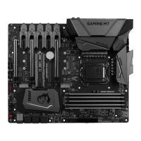
MSI Z170A GAMING M7 Specifications

General IconGeneral
ChipsetIntel Z170
CPU SocketLGA 1151
Memory Slots4 x DIMM
Maximum Memory64GB
Form FactorATX
AudioRealtek ALC1150
M.2 Slots1
USB 3.1 Gen1 Ports8
PCI Express x16 Slots3
PCI Express x1 Slots4
RAID SupportRAID 0, 1, 5, 10
Multi-GPU SupportAMD 3-Way CrossFire, NVIDIA 2-Way SLI
Storage Interface6 x SATA 6Gb/s
USB Ports8 x USB 3.1 Gen1
LANKiller E2400 Gigabit LAN Controller

Related product manuals