Temposonics
®
E-Series CANopen
Operation Manual
11
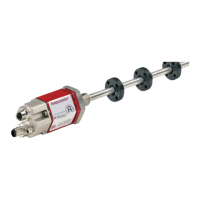
4.2 Styles and installation of E-Series EP
Magnet
50 (2)
68 (2.68)
Null zone
13
(0.52)
14.6
(0.57)
Stroke length
50…2540
(2…100)
Dead zone
68
(2.68)
31
(1.22)
43.4
(1.71)
35.6 (1.4)
Sensor electronics housing
48.8
(1.92)
35
(1.38)
Controlling design dimensions are in millimeters and measurements in ( ) are in inches
Unless otherwise stated, apply to the general tolerances according to DIN ISO 2768-m
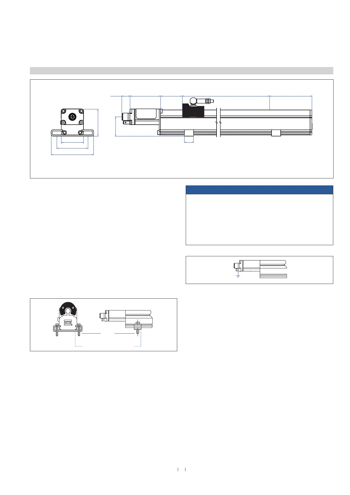
Installation of EP
The position sensor can be installed in any position. Normally, the
sensor is firmly installed and the position magnet is fastened to
the mobile machine part. Thus it can travel along the sensor rod
contactlessly.
The sensor is fitted on a flat machine surface using mounting clamps
(Fig. 4). A length-dependent number of these clamps are delivered
with the sensor and must be distributed over the profile at regular
distances.
For fastening, we recommend using M5×20 screws according to
DIN 6912 that should be tightened with a maximum fastening torque
of 5 Nm.
Adjustable mounting clamps
M5×20
max. 5 Nm
Fig. 3: Temposonics
®
E-Series EP
NOTICE
Do not mount the sensors in the area of strong magnetic or electric
noise fields. Take care to mount the sensor in an axially parallel
position to avoid damaging the carriage, magnet and sensor rod.
The sensor is isolated from the machine ground. For this reason,
grouding via grounding lug on the sensor electronics housing is
indispensable (Fig. 5).
Fig. 4: Mounting clamps with cylinder screw M5×20, fastening torque ≤ 5 Nm
on a Temposonics
®
E-Series EP sensor with U-magnet
Fig. 5: Grounding profile sensor

 Loading...