Chapter 9 Counters
NI USB-621x User Manual 9-26 ni.com
Counter n Source Signal
The selected edge of the Counter n Source signal increments and
decrements the counter value depending on the application the counter is
performing. Table 9-4 lists how this terminal is used in various
applications.
Routing a Signal to Counter n Source
Each counter has independent input selectors for the Counter n Source
signal. Any of the following signals can be routed to the Counter n Source
input.
•80MHz Timebase
•20MHz Timebase
• 100 kHz Timebase
• PFI <0..3>, PFI <8..11>
In addition, Counter 1 TC or Counter 1 Gate can be routed to
Counter 0 Source. Counter 0 TC or Counter 0 Gate can be routed to
Counter 1 Source.
Some of these options may not be available in some driver software.
Routing Counter n Source to an Output Terminal
You can route Counter n Source out to any PFI <4..7> or PFII <12..15>
terminal.
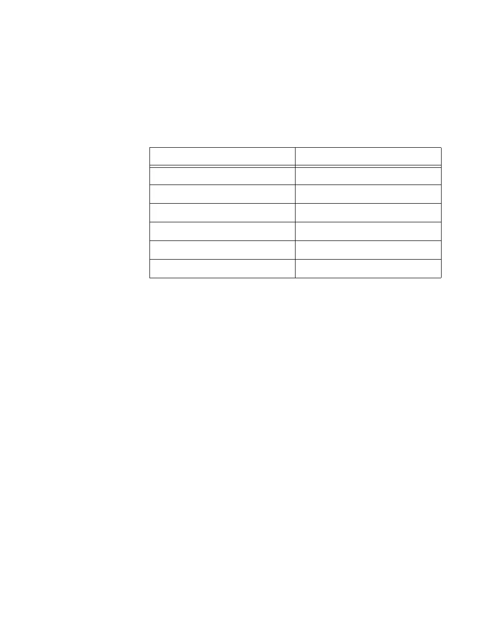
Table 9-4. Counter Applications and Counter n Source
Application Purpose of Source Terminal
Pulse Generation Counter Timebase
One Counter Time Measurements Counter Timebase
Two Counter Time Measurements Input Terminal
Non-Buffered Edge Counting Input Terminal
Buffered Edge Counting Input Terminal
Two-Edge Separation Counter Timebase

 Loading...


