Chapter 10 PFI
NI USB-621x User Manual 10-4 ni.com
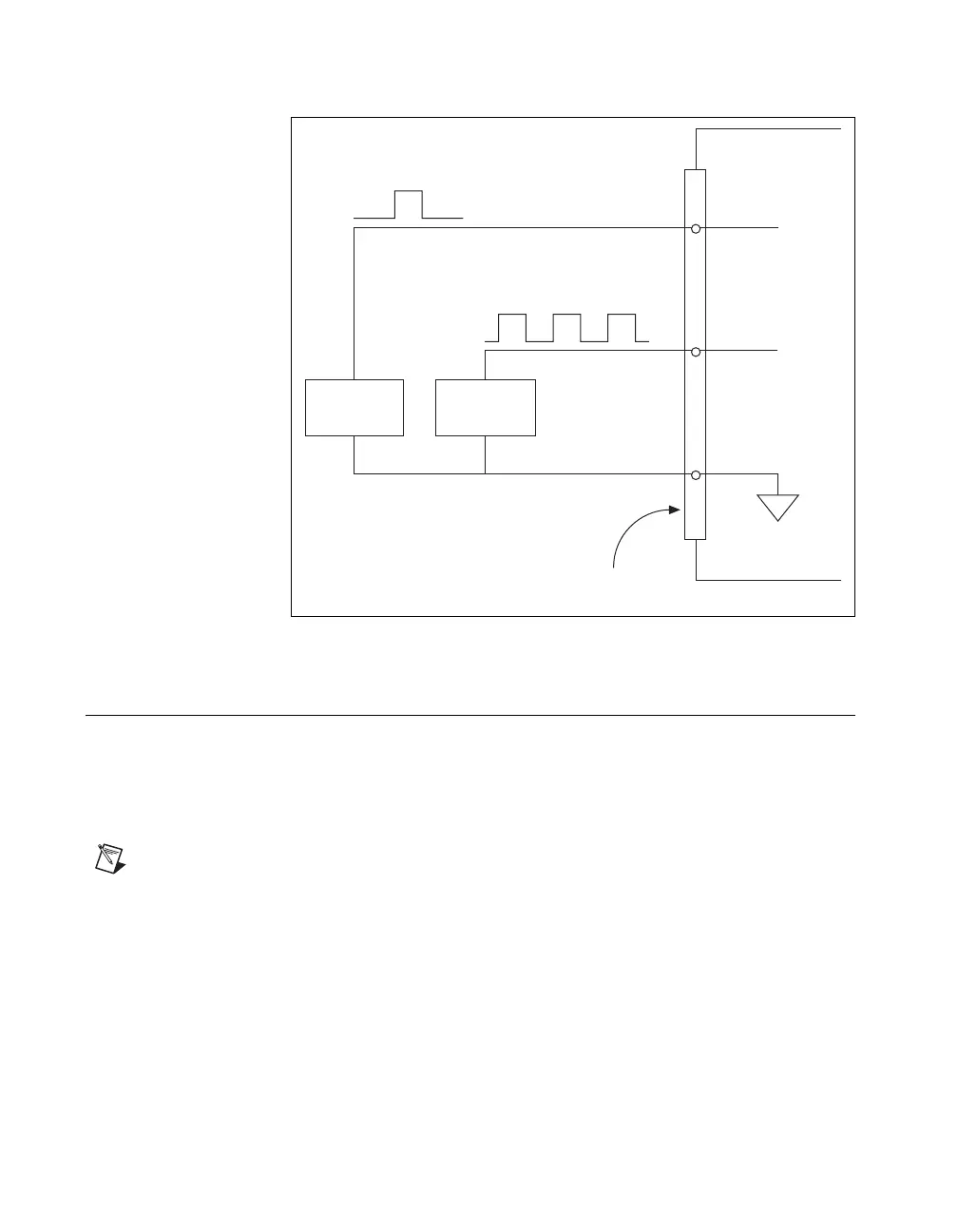
Figure 10-3. PFI Input Signals Connections
PFI Filters
You can enable a programmable debouncing filter on each PFI signal.
When the filters are enabled, your device samples the input on each rising
edge of a filter clock. M Series devices use an onboard oscillator to
generate the filter clock with a 40 MHz frequency.
Note NI-DAQmx only supports filters on counter inputs.
The following is an example of low to high transitions of the input signal.
High to low transitions work similarly.
Assume that an input terminal has been low for a long time. The input
terminal then changes from low to high, but glitches several times. When
the filter clock has sampled the signal high on N consecutive edges, the low
to high transition is propagated to the rest of the circuit. The value of N
depends on the filter setting; refer to Table 10-1.
PFI 0
Source
PFI 2
Source
M Series Device
D GND
PFI 2
PFI 0
I/O Connctor

 Loading...


