Chapter 8 Digital I/O
© National Instruments Corporation 8-3 NI USB-621x User Manual
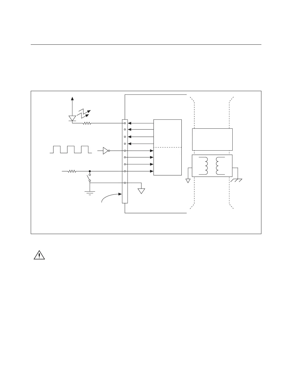
Connecting Digital I/O Signals
The DI and DO signals, P0.<0..7> and P1.<0..7> are referenced to D GND.
Digital input applications include receiving TTL signals and sensing
external device states, such as the state of the switch shown in the figure.
Digital output applications include sending TTL signals and driving
external devices, such as the LED shown in Figure 8-2.
Figure 8-2. Digital I/O Connections
Caution Exceeding the maximum input voltage ratings, which are listed in the
specifications document for each M Series device, can damage the DAQ device and the
computer. NI is not liable for any damage resulting from such signal connections.
+5
LED
TTL Signal
+5 V
Switch
I/O Connector
D GND
M Series Device
P0.<0..3>
P1.<0..3>
Digital
Isolators
Isolation
Barrier
(USB-6215
and USB-6218
devices only)
1
1
When using a USB-6215/6218, you must connect D GND
and/or AI GND to the local ground on your system.

 Loading...


