Chapter 4 Analog Input
NI USB-621x User Manual 4-20 ni.com
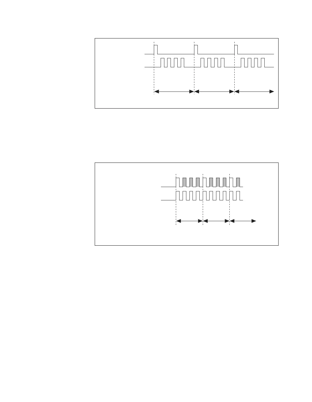
Figure 4-13. ai/SampleClock and ai/ConvertClock Properly Matched
It is also possible to use a single external signal to drive both
ai/SampleClock and ai/ConvertClock at the same time. In this mode, each
tick of the external clock will cause a conversion on the ADC. Figure 4-14
shows this timing relationship.
Figure 4-14. Single External Signal Driving ai/SampleClock and ai/ConvertClock
Simultaneously
AI Convert Clock Timebase Signal
The AI Convert Clock Timebase (ai/ConvertClockTimebase) signal is
divided down to provide on of the possible sources for ai/ConvertClock.
Use one of the following signals as the source of
ai/ConvertClockTimebase:
• ai/SampleClockTimebase
• 20 MHz Timebase
ai/ConvertClockTimebase is not available as an output on the I/O
connector.
• Properly Matched Sample Clock and Convert Clock
ai/SampleClock
ai/ConvertClock
Sample #1 Sample #2 Sample #3
Channel Measured 1 2 3 0
1 2 3 0 1 2 3 0
• One External Signal Driving Both Clocks
ai/SampleClock
ai/ConvertClock
Sample #1 Sample #2 Sample #3
1230
12301…0
Channel Measured

 Loading...


