6-20 | ni.com
Chapter 6 Digital I/O
The Change Detection Event signal can do the following:
• Drive any RTSI <0..7>, PFI <0..15>, or PXI_STAR signal
• Drive the DO Sample Clock or DI Sample Clock
• Generate an interrupt
The Change Detection Event signal can also be used to detect changes on digital output events.
DI Change Detection Applications
The DIO change detection circuitry can interrupt a user program when one of several DIO
signals changes state.
You can also use the output of the DIO change detection circuitry to trigger a DI or counter
acquisition on the logical OR of several digital signals. To trigger on a single digital signal, refer
to the
Triggering with a Digital Source section of Chapter 11, Triggering. By routing the Change
Detection Event signal to a counter, you can also capture the relative time between bus changes.
You can also use the Change Detection Event signal to trigger DO or counter generations.
Digital Filtering
You can enable a programmable debouncing filter on each digital line on Port 0. When the filters
are enabled, your device samples the input on each rising edge of a filter clock. X Series devices
divide down the onboard 100 MHz or 100 kHz clocks to generate the filter clock. The following
is an example of low-to-high transitions of the input signal. High-to-low transitions work
similarly.
Assume that an input terminal has been low for a long time. The input terminal then changes
from low-to-high, but glitches several times. When the filter clock has sampled the signal high
on two consecutive edges and the signal remained stable in between, the low-to-high transition
is propagated to the rest of the circuit.
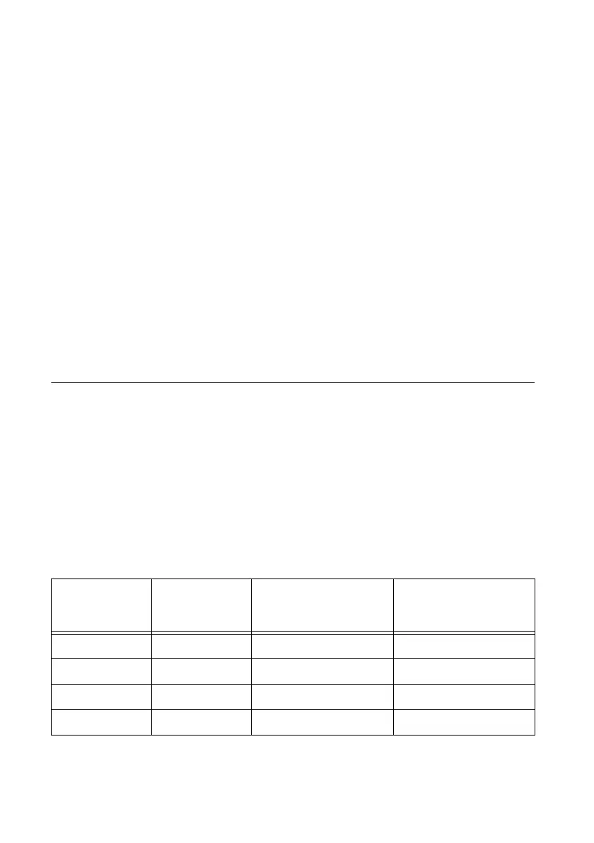
Table 6-1. Filters
Filter Setting Filter Clock
Pulse Width
Guaranteed to Pass
Filter
Pulse Width
Guaranteed to Not
Pass Filter
Short 12.5 MHz 160 ns 80 ns
Medium 195.3125 kHz 10.24 µs 5.12 µs
High 390.625 Hz 5.12 ms 2.56 ms
None — — —

 Loading...


