© National Instruments | 8-1
8
PFI
X Series devices have up to 16 Programmable Function Interface (PFI) signals. In addition,
X Series devices have up to 32 lines of bidirectional DIO signals.
Each PFI can be individually configured as the following:
• A static digital input
• A static digital output
• A timing input signal for AI, AO, DI, DO, or counter/timer functions
• A timing output signal from AI, AO, DI, DO, or counter/timer functions
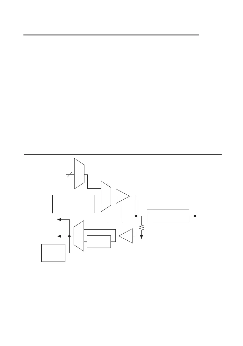
Each PFI input also has a programmable debouncing filter. Figure 8-1 shows the circuitry of
one PFI line. Each PFI line is similar.
Figure 8-1. X Series PFI Circuitry
When a terminal is used as a timing input or output signal, it is called PFI x (where x is an integer
from 0 to 15). When a terminal is used as a static digital input or output, it is called P1.x or P2.x.
On the I/O connector, each terminal is labeled PFI x/P1.x or PFI x/P2.x.
The voltage input and output levels and the current drive levels of the PFI signals are listed in
the device specifications
Timing Signals
Direction
Control
I/O Protection
Weak Pull-Down
PFI
x/P1/P2
Static DO
Buffer
To Input Timing
Signal Selectors
PFI
Filters
Static DI
PFI
Change
Detection

 Loading...


