6-24 | ni.com
Chapter 6 Digital I/O
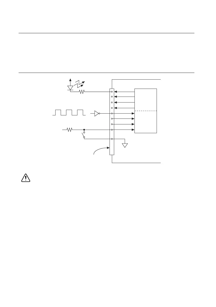
Connecting Digital I/O Signals
The DIO signals, P0.<0..31>, P1.<0..7>, and P2.<0..7> are referenced to D GND. You can
individually program each line as an input or output. Figure 6-16 shows P1.<0..3> configured
for digital input and P1.<4..7> configured for digital output. Figure 6-16 shows the switch
receiving TTL signals and sensing external device states and shows the LED sending TTL
signals and driving external devices.
Figure 6-16. Digital I/O Connections
Caution Exceeding the maximum input voltage ratings, which are listed in each
X Series device specifications, can damage the DAQ device and the computer. NI is
not liable for any damage resulting from such signal connections.
+5 V
LED
TTL Signal
+5 V
Switch
I/O Connector
D GND
X Series Device
P1.<0..3>
P1.<4..7>

 Loading...


