EasyManuals Logo
Home>National Instruments>I/O Systems>PCIe-6323

National Instruments PCIe-6323 User Manual

National Instruments PCIe-6323
278 pages
To Next Page IconTo Next Page
To Previous Page IconTo Previous Page
Page #193 background imageLoading...
Page #193 background image
© National Instruments | 9-5
X Series User Manual
RTSI Connector Pinout
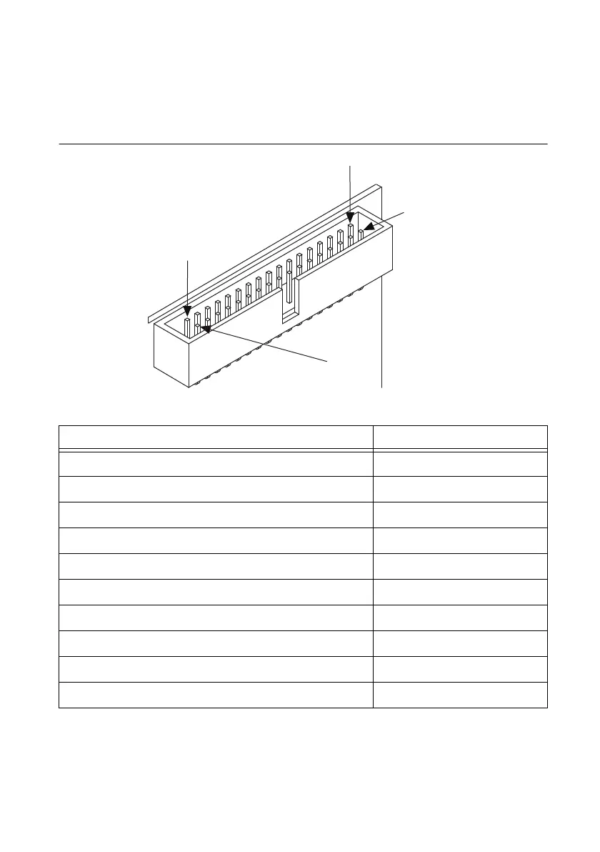
(NI PCI Express Devices) Figure 9-2 shows the RTSI connector pinout and Table 9-1
describes the RTSI signals.
Figure 9-2. PCI Express RTSI Pinout
Table 9-1. RTSI Signals
RTSI Bus Signal Terminal
RTSI 7 34
RTSI 6 32
RTSI 5 30
RTSI 4 28
RTSI 3 26
RTSI 2 24
RTSI 1 22
RTSI 0 20
Not Connected. Do not connect signals to these terminals. 1 through 18
D GND 19, 21, 23, 25, 27, 29, 31, 33
Terminal 1
Te r m i nal 2
Terminal 34
Terminal 33

Table of Contents

Questions and Answers:

Question and Answer IconNeed help?

Do you have a question about the National Instruments PCIe-6323 and is the answer not in the manual?

National Instruments PCIe-6323 Specifications

General IconGeneral
BrandNational Instruments
ModelPCIe-6323
CategoryI/O Systems
LanguageEnglish

Related product manuals