4-20 | ni.com
Chapter 4 Analog Input
Using Non-Referenced Single-Ended (NRSE) Connections for
Ground-Referenced Signal Sources
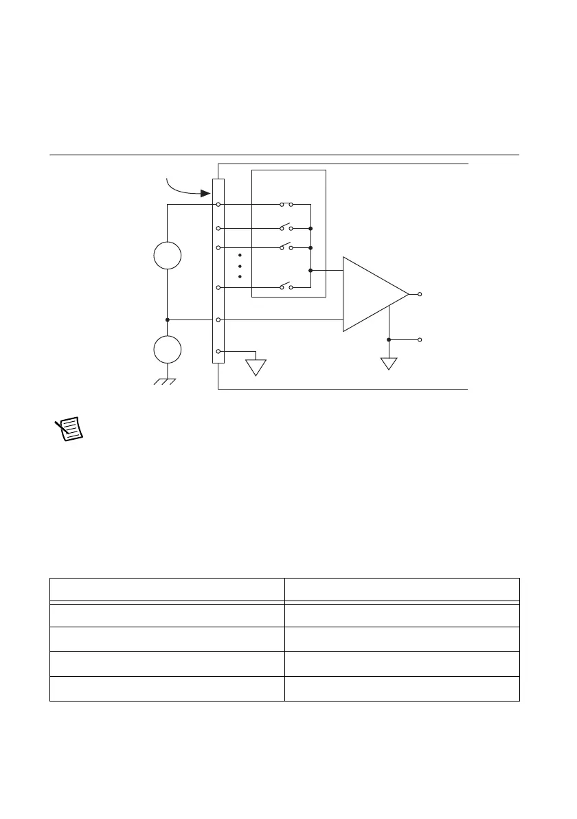
Figure 4-11 shows how to connect ground-reference signal sources in NRSE mode.
Figure 4-11. Single-Ended Connections for
Ground-Referenced Signal Sources (NRSE Configuration)
Note (NI USB-6341/6343/6346/6361/6363 BNC Devices) To measure a
ground-referenced signal source on X Series USB BNC devices, move the switch
under the BNC connector to the GS position.
AI <0..31> and AI SENSE must both remain within ±11 V of AI GND.
To measure a single-ended, ground-referenced signal source, you must use the NRSE
ground-reference setting. Use Table 4-4 to determine how to correctly connect your AI signal.
AI SENSE is internally connected to the negative input of the NI-PGIA. Therefore, the ground
point of the signal connects to the negative input of the NI-PGIA.
Table 4-4. AI Signal Connections
Signal Ground-Reference
AI <0..15> AI SENSE
AI <16..79> AI SENSE 2
AI <80..143> AI SENSE 3
AI <144..207> AI SENSE 4
MIO X Series Device Configured in NRSE Mode
Input Multiplexers
I/O Connector
AI GND
AI SENSE
AI <0..x>
–
+
–
+
V
cm
V
s
Ground-
Referenced
Signal
Source
Common-
Mode
Noise
and Ground
Potential
PGIA
–
+
–
+
V
m
Measured
Voltage
Instrumentation
Amplifier

 Loading...


