© National Instruments | 7-7
X Series User Manual
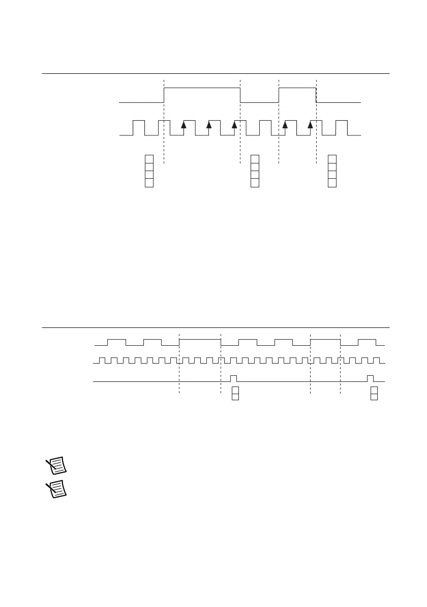
Figure 7-6 shows an example of an implicit buffered pulse-width measurement.
Figure 7-6. Implicit Buffered Pulse-Width Measurement
Sample Clocked Buffered Pulse-Width Measurement
A Sample Clocked Buffered pulse-width measurement is similar to single pulse-width
measurement, but buffered pulse-width measurement takes measurements over multiple pulses
correlated to a sample clock.
The counter counts the number of edges on the Source input while the Gate input remains active.
On each sample clock edge, the counter stores the count in the FIFO of the last pulse width to
complete. A DMA controller transfers the stored values to host memory.
Figure 7-7 shows an example of a sample clocked buffered pulse-width measurement.
Figure 7-7. Sample Clocked Buffered Pulse-Width Measurement
Hardware-Timed Single Point Pulse-Width Measurement
A hardware-timed single point (HWTSP) pulse-width measurement has the same behavior as a
sample clocked buffered pulse-width measurement.
Note If a pulse does not occur between sample clocks, an overrun error occurs.
Note (NI USB-634
x/635x/636x Devices) USB X Series devices do not support
hardware-timed single point (HWTSP) operations.
For information about connecting counter signals, refer to the
Default Counter/Timer Pins
section.
SOURCE
GATE
Counter Value
Buffer
10 3
3
2
212
3
3
2
Gate
Source
Sample Clock
2
3
42
4
3
2
2
4
Buffer

 Loading...


