EasyManuals Logo
Home>National Instruments>Chassis>PXI Series

National Instruments PXI Series User Manual

National Instruments PXI Series
89 pages
To Next Page IconTo Next Page
To Previous Page IconTo Previous Page
Page #49 background imageLoading...
Page #49 background image
Chapter 3 I/O Information
© National Instruments 3-5 NI PXI-8109 User Manual
COM1
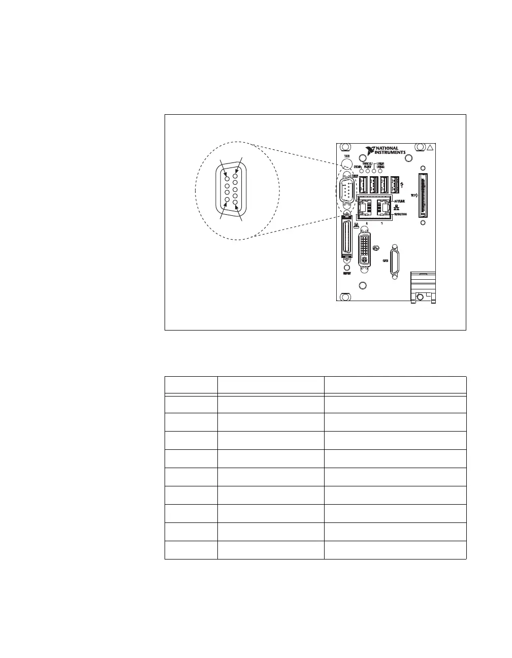
Figure 3-3 shows the location and pinouts for the COM1 connector on the
NI PXI-8109. Table 3-3 lists and describes the COM1 connector signal.
Figure 3-3. COM1 Connector Location and Pinout
Table 3-3. COM1 Connector Signals
Pin Signal Name Signal Description
1 DCD Data Carrier Detect
2 RXD Receive Data
3 TXD Transmit Data
4 DTR Data Terminal Ready
5 GND Ground
6 DSR Data Set Ready
7 RTS Ready to Send
8 CTS Clear to Send
9 RI Ring Indicator
NI PXI-8109
Embedded Controller
6
9
5
1
COM1

Table of Contents

Other manuals for National Instruments PXI Series

Questions and Answers:

Question and Answer IconNeed help?

Do you have a question about the National Instruments PXI Series and is the answer not in the manual?

National Instruments PXI Series Specifications

General IconGeneral
BrandNational Instruments
ModelPXI Series
CategoryChassis
LanguageEnglish

Related product manuals