Chapter 3 I/O Information
© National Instruments 3-11 NI PXI-8109 User Manual
GPIB (IEEE 488.2)
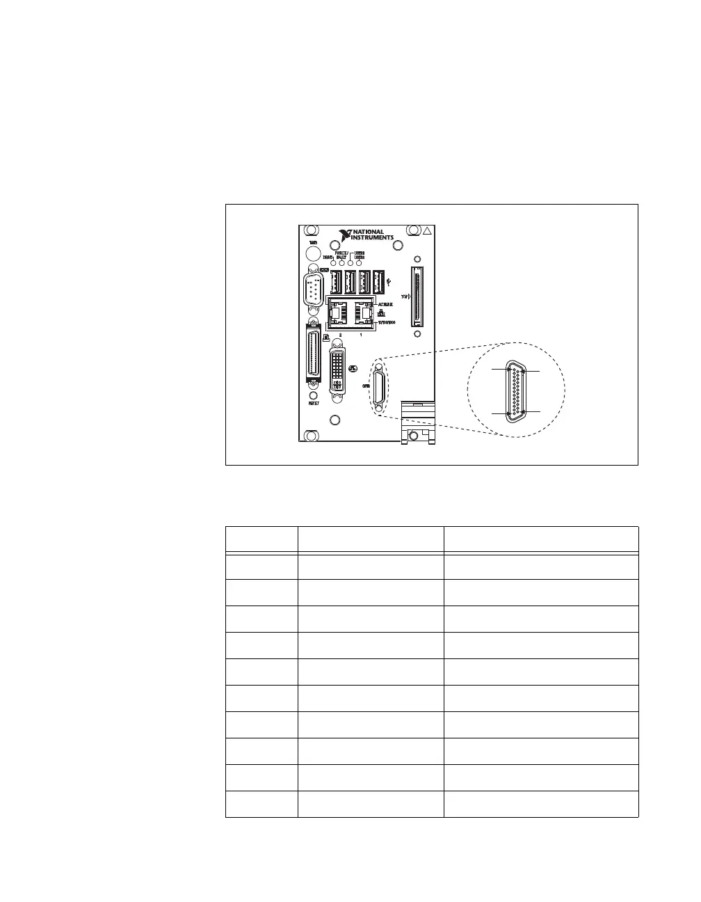
Figure 3-8 shows the location and pinouts for the GPIB connector on
the NI PXI-8109. Table 3-9 lists and describes the GPIB connector signals.
National Instruments provides a GPIB mating connector, part
number 183285-0R2.
Figure 3-8. GPIB Connector Location and Pinout
Table 3-9. GPIB Connector Signals
Pin Signal Name Signal Description
1 DIO1# Data Bit 1
2 DIO2# Data Bit 2
3 DIO3# Data Bit 3
4 DIO4# Data Bit 4
5 EOI# End or Identify
6 DAV# Data Valid
7 NRFD# Not Ready for Data
8 NDAC# Not Data Accepted
9 IFC# Interface Clear
10 SRQ# Service Request
NI PXI-8109
Embedded Controller
GPIB
25
14
1
13
 Loading...