10 – ENGLISH
EN
4.2.5 Operations for connection
To make the electrical connections (“Figure 7”):
1. remove the terminals from their housings
2. connect the various devices to the relevant terminals ac-
cording to the diagram shown in “Figure 7”
3. put the terminals back into their housings.
m
If the system includes a single gearmotor only, con-
nect it to terminal M2 and leave terminal M1 free.
4.2.6 Positioning the safety cable clamp
Once the connections to the control unit have been made, the
cables of the power connections must be secured with the rele-
vant cable clamp (“Figure 10”).
To do this:
1. remove the cable clamp (A) from its original position
2. place the cable clamp (A) over the connection cables to
be secured and fasten it with the two screws (B).
A
B
10
4.3 CONNECTING OTHER DEVICES TO THE
CONTROL UNIT
In any additional devices belonging to the system (e.g. tran-
sponder card reader, light for the key selector, etc.) must be
powered, they can be connected to the control unit using ter-
minals “3 - 0 V” and “4 - Common” (“Figure 7”). The power
supply voltage is 24 Vc with a maximum available current of
200 mA.
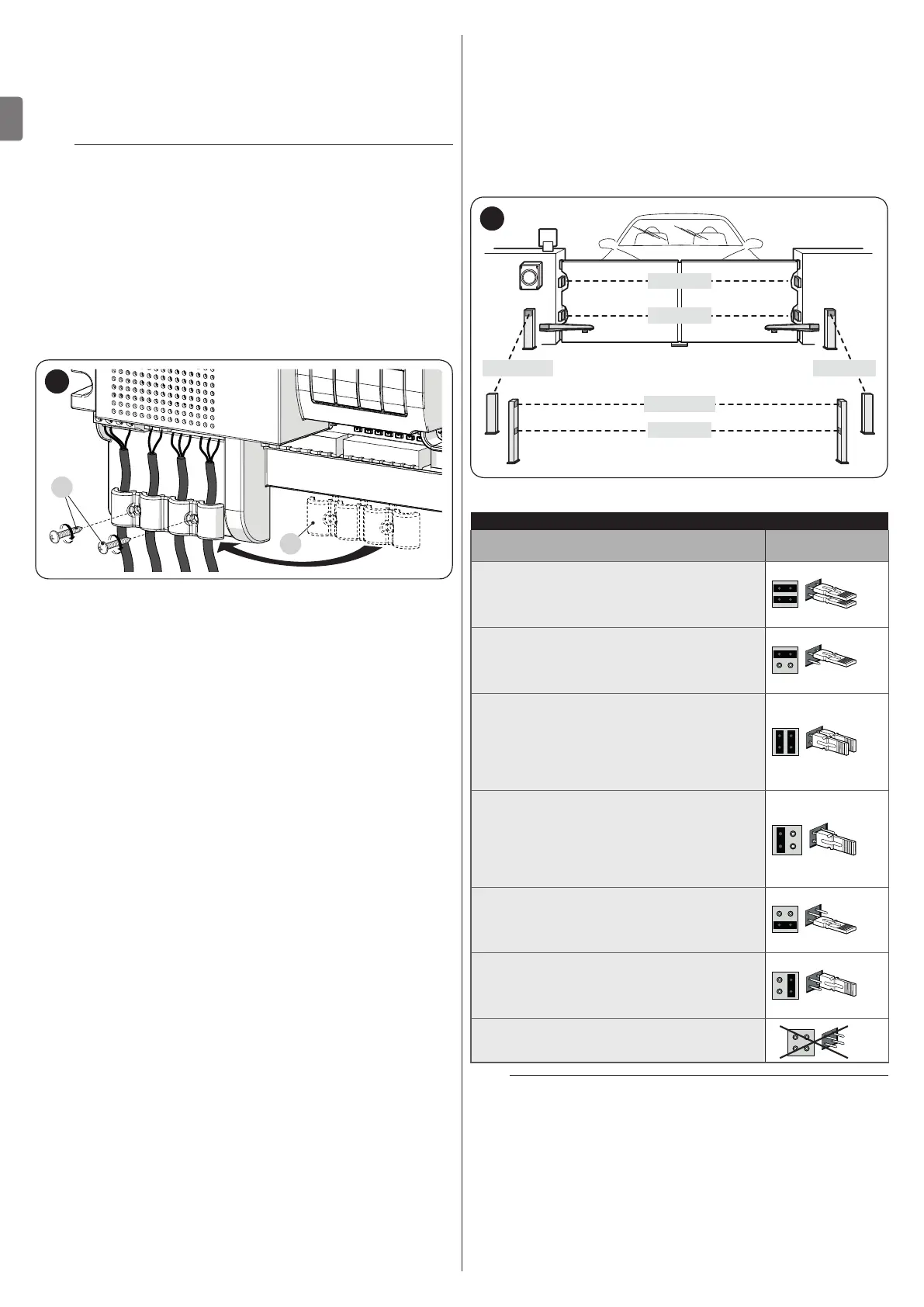
4.4 ADDRESSING OF DEVICES CONNECTED
WITH THE BLUEBUS SYSTEM
To allow the control unit to recognise the devices connected
through the “BlueBUS” system, these devices must be ad-
dressed.
This operation can be carried out by correctly positioning the
electrical jumper present in each device (also refer to the in-
struction manual of each device). Shown below is an address-
ing diagram for photocells, based on their type.
FOTO 1
FOTO
FOTO II
FOTO 1 II
FOTO 2 II FOTO 2
11
Table 3
PHOTOCELL ADDRESSES
Photocell
Position of the
jumpers
FOTO (PHOTO)
External photocell h = 50 activated during
the closing phase (stops and reverses the
gate’s movement)
FOTO II (PHOTO II)
External photocell h = 100 activated during
the closing phase (stops and reverses the
gate’s movement)
FOTO 1 (PHOTO 1)
Internal photocell h = 50 cm with activation
both during closing (stops and reverses
the movement) and during opening
(stops and restarts when the photocell
disengages)
FOTO 1 II (PHOTO 1 II)
Internal photocell h = 100 cm with
activation both during closing (stops
and reverses the movement) and during
opening (stops and restarts when the
photocell disengages)
FOTO 2 (PHOTO 2)
Internal photocell triggered during the
opening phase (stops and reverses the
gate’s movement)
FOTO 2 II (PHOTO 2 II)
Internal photocell triggered during the
opening phase (stops and reverses the
gate’s movement)
FOTO 3 (PHOTO 3)
CONFIGURATION NOT ALLOWED
m
At the end of the installation procedure, or after
photocells or other devices have been removed, it is
necessary to complete the learning procedure (see
the “Learning of connected devices” paragraph).

 Loading...


