ENGLISH – 11
EN
4.5 INITIAL START-UP AND ELECTRICAL
CONNECTIONS TEST
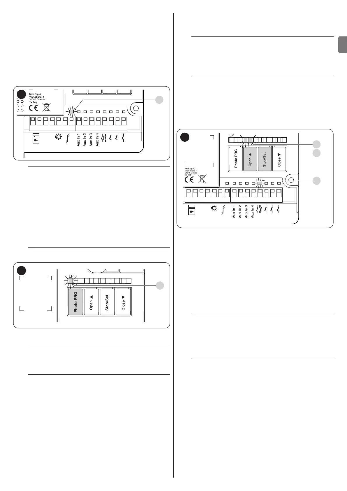
After powering the control unit, carry out the following checks
(“Figure 12”):
1. after a few seconds, check that the “Bluebus” (A) LED
ashes regularly with one ash per second
2. check that the LEDs of the photocells, both TX (transmis-
sion) and RX (reception), ash. The type of ash emitted
in this phase is not signicant
3. check that the warning light connected to the “Flash” out-
put is turned off.
0V
EL
OGI
Bluebus
2
Close
Open
SbS
Stop
1 2 3 4 5 6 7 8 9 10 11 12 13 14 15
A
12
a
If any one of these tests fails, disconnect the pow-
er supply to the control unit and check the various
electrical connections made previously.
4.5.1 Programming with relay photocells
If relay photocells have been connected to the control unit to
inputs AUX 1 (PHOTO), AUX 2 (PHOTO 1) and AUX 3 (PHOTO
2), the “Photocell programming” function must be activated.
To do this:
– press and hold the Photo PRG button until the “LP” LED
switches on.
l
Any inputs not used must be kept free.
L5 L6 L7 L8L4L3L2L1
LP
13
To deactivate the “Photocell programming” function, press the
Photo PRG button until the “LP” LED switches off.
l
If the “Photocell programming” function is activat-
ed (“LP” LED lit), inputs AuxIn1, AuxIn2, AuxIn3,
AuxIn4 cannot be used as limit switches.
l
For further details on the operation with and without
the phototest, consult the wiring diagrams under
the “Wiring diagram with relay photocells without
phototest” and “Wiring diagram with relay photo-
cells with phototest” paragraphs.
4.6 LEARNING OF CONNECTED DEVICES
After the initial start-up, the control unit must recognise the de-
vices connected to the “Bluebus” and “Stop” inputs.
l
The control unit automatically learns the relay pho-
tocells connected to inputs AUX1, AUX2 and AUX3
only if the operation described under the “Program-
ming with relay photocells” paragraph has been en-
abled.
l
The learning phase must be carried out even if no
device is connected to the control unit.
The control unit can individually recognise the various devices
connected, thanks to the learning procedure, and detect possi-
ble anomalies.
For this to occur, the device learning procedure must be carried
out whenever a device is added or removed.
L5 L6 L7 L8L4L3L2L1
0V
EL
OGI
2
SbS
Stop
1 2 3 4 5 6 7 8 9 10 11 12 13 14 15
S
L1
L2
14
LEDs “L1” and “L2” on the control unit (“Figure 14”) emit some
slow ashes to signal that the learning procedure must be car-
ried out.
To do this:
1. simultaneously press and hold the
f
and
g
buttons
2. release the buttons when LEDs “L1” and “L2” start ash-
ing quickly (after roughly 3 seconds)
3. wait a few seconds until the control unit has completed the
device learning phase
4. once this phase terminates, the “Stop” (S) LED must be lit
and LEDs “L1” and “L2” must switch off (LEDs “L3” and
“L4” could start ashing).
l
If the AUX In 1-2-3 inputs are used to connect the
relay photocells, leave any inputs not used free.
4.7 SELECTING THE TYPE OF MOTOR (FOR
HYDRAULIC MOTORS ONLY)
m
This phase must only be carried out if hydraulic mo-
tors are connected to the control unit.
In hydraulic actuators, the thrust to keep the gate closed is gen-
erated within a hydraulic circuit that remains constantly under
pressure. When time and wear reduce the hydraulic circuit’s
tightness, after a few hours it may occur that the internal pres-
sure decreases, potentially causing the gate leaves to open
slightly. To overcome this problem, the control unit has a “Pres-
sure maintenance” function that, if activated, every 4 hours that
the gate has been closed triggers a brief “close” command in
order to fully close the leaves and reload the pressure of the
hydraulic circuit. To activate the function, refer to the “Level 1
programming (ON-OFF) - Function L8” paragraph.

 Loading...


