ENGLISH – 17
EN
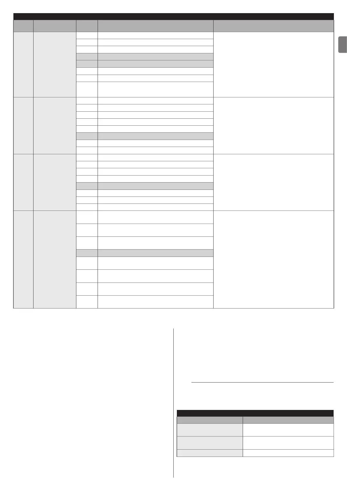
LEVEL 2 FUNCTIONS (ADJUSTABLE PARAMETERS)
Entry
LED
Parameter
LED
(level)
Set value Description
L5 Balancing
L1 0% - Decreases the closing duration Allows for increasing or decreasing the duration
of the closing manoeuvre. This is useful when
the motor moves in the two directions at different
speeds (for example, hydraulic motors) or when
the leaves are unbalanced and require different
force levels during the opening and closing
manoeuvres, covering the same distance with
different times.
If the closing manoeuvre must be increased, shift
the setting towards L8; if the closing manoeuvre
must be decreased, shift the setting towards L1.
L2 20 %
L3 30 %
L4 40 %
L5 60 %
L6 70 %
L7 80 %
L8 100% - Increases the closing duration
L6 Motor force
L1 25% - Minimum force
Adjusts the force of both motors through the
phase partialisation expressed in percentage.
L2 35 %
L3 45 %
L4 55 %
L5 65 %
L6 75 %
L7 85 %
L8 100% - Maximum force
L7 Start-up time
L1 0 s
Allows for programming the start-up duration at
the start of a manoeuvre.
L2 0.5 s
L3 1 s
L4 1.5 s
L5 1.8 s
L6 2 s
L7 2.5 s
L8 3 s
L8
Pedestrian or
partial opening
L1
Pedestrian 1 (the M2 gate leaf opens to 1/4 of
the full length)
Adjusts the type of opening associated with the
“partial opening 1” command.
In levels L5, L6, L7 and L8, “minimum” opening
refers to the smallest opening between M1 and
M2; for example, if M1 opens to 90° and M2
opens to 110°, the minimum opening is 90°.
L2
Pedestrian 2 (the M2 gate leaf opens to 1/2 of
the full length)
L3
Pedestrian 3 (the M2 gate leaf opens to 3/4 of
the full length)
L4 Pedestrian 4 (full opening of gate leaf 2)
L5
Partial 1 (the two gate leaves open to 1/4 of the
“minimum” opening level)
L6
Partial 2 (the two gate leaves open to 1/2 of the
“minimum” opening level)
L7
Partial 3 (the two gate leaves open to 3/4 of the
“minimum” opening level)
L8
Partial 4 (the two gate leaves open to the
“minimum” opening level)
6.4 SPECIAL FUNCTIONS
6.4.1 “Move anyway” function
This function can be used to operate the automation even one
or more some safety devices fail to work properly or are out of
order. The automation can be controlled in “hold-to-run” mode
by proceeding as follows:
1. send a command to operate the gate, using a transmitter
or key selector, etc. If everything functions properly, the
gate will move normally, otherwise proceed with point 2
2. within 3 seconds, press the control again and hold it down
3. after roughly 2 seconds, the gate will complete the re-
quested manoeuvre in “hold-to-run” mode, in other
words, it will continue to move so long as the control is
held down.
6.4.2 “Maintenance notice” function (congurable with
an external programmer)
This function allows for signalling to the user when the auto-
mation needs maintenance. The maintenance signal is given
through a lamp connected to the “OGI” output, if this output is
congured as a “Maintenance indicator”.
The conguration is only possible through the “Oview” program-
mer (refer to the “Connecting the IBT4N interface” paragraph).
l
The various indicator lamp signals are shown in “
Table 7”.
Table 7
“MAINTENANCE INDICATOR” SIGNAL
Number of manoeuvres Signal
Below 80% of the limit
Lamp stays lit for 2 seconds at the
start of the opening manoeuvre.
Between 81% and 100%
of the limit
Lamp ashes for the entire duration
of the manoeuvre.
Over 100% of the limit
Lamp ashes continuously.

 Loading...


