ENGLISH – 5
EN
TECHNICAL SPECIFICATIONS OF ELECTRICAL CABLES
Identication
no.
Cable characteristics
g
ELECTRIC LOCK CONNECTION cable
1 cable 2 x 1 mm
2
Maximum length 10 m
Note 1 If the power supply cable is longer than 30 m, a cable
with larger cross-sectional area (3 x 2.5 mm
2
) must be
used and a safety earthing system must be installed
near the automation.
Note 2 If the BlueBus cable is longer than 20 m, up to maximum
40 m, a cable with larger gauge (2 x 1 mm
2
) must be
used.
a
The cables used must be suited to the type of envi-
ronment of the installation site.
a
When laying the ducting for routing the electrical
cables and for the cable entry point into the control
unit housing, check that there are no water depos-
its in the junction wells nor condensate in the con-
nection ducts, as water and damp conditions could
damage the product’s electronic circuits.
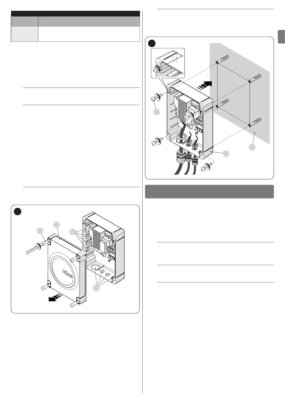
3.5 INSTALLING THE CONTROL UNIT
To secure the control unit (“Figure 5” and “Figure 6”):
1. loosen the screws (A) and remove the cover (B) of the
control unit
2. identify the pre-cut holes (C) located along the lower side
of the box and perforate the ones used to pass the elec-
trical cables
l
If necessary, the side cable entry can be used (D). In
this case, suitable tube ttings must be used.
B
C
D
A
5
3. drill the wall (E) by observing the measurements shown in
the gure and arrange suitable wall plugs (not supplied)
4. position the box (F) and fasten it with the screws (G) (not
supplied)
5. arrange cable glands for passing the connecting cables
6. make the electrical connections by operating as de-
scribed in the “ELECTRICAL CONNECTIONS” chapter.
l
To install any other devices used on the automated
system, refer to the respective instruction manuals.
7. after making the electrical connections, put the cover (B)
back on and tighten the screws (A).
205 mm
245 mm
E
G
F
6
ELECTRICAL CONNECTIONS
4
4 ELECTRICAL CONNECTIONS
4.1 PRELIMINARY CHECKS
The electrical connection of the various devices present on
the automation (photocells, digital keypads, transponder card
readers, etc.) to the control unit must be made through the Nice
“Bluebus” system. For the other connections, refer to that spec-
ied below.
f
All electrical connections must be made with the
system disconnected from the mains electricity and
with the back-up battery (if present) disconnected.
a
The connection operations must only be carried out
by qualied personnel.
f
Mount a device on the electric power line that com-
pletely disconnects the automation from the grid.
– The disconnection device must have contacts with a
sufcient gap to ensure complete disconnection, under
the Category III overvoltage conditions, in accordance
with the installation instructions. If necessary, this de-
vice guarantees quick and safe disconnection from the
mains power and therefore must be positioned in sight
of the automation. If located in a concealed position,
it must be equipped with a system that prevents inad-
vertent or unauthorised reconnection of power, to avoid
potential hazards.

 Loading...


