14 – ENGLISH
EN
TESTING AND COMMISSIONING
5
5 TESTING AND COMMISSIONING
These are the most important phases of the automation’s con-
struction, as they ensure maximum safety of the system. The
test can also be used to periodically verify the devices making
up the automation.
m
Testing and commissioning of the automation must
be performed by skilled and qualied personnel,
who are responsible for the tests required to ver-
ify the solutions adopted according to the risks
present, and for ensuring that all legal provisions,
standards and regulations are met, in particular all
the requirements of the EN 12445 standard, which
denes the test methods for checking gate automa-
tions.
The additional devices must undergo specic testing, both in
terms of their functions and their proper interaction with the con-
trol unit. Refer to the instruction manuals of the individual devic-
es.
5.1 TESTING
The sequence of steps to be performed when running the test-
ing phase, as described below, refers to a typical system (“Fig-
ure 3”).
To run the test:
1. verify that all the instructions stated in the “GENERAL
SAFETY WARNINGS AND PRECAUTIONS” chapter
have been strictly observed
2. unlock the motors for the manual manoeuvre as described
in the respective instruction manual. Move the gate man-
ually and verify whether the leaves can be opened and
closed with a force below 390 N
3. lock the motors as described in the respective instruction
manual
4. using the control devices (transmitter, control button, key
selector, etc.), test the gate’s opening, closing and stop-
page movements to make sure that the leaves move as
intended. Several tests should be carried out to assess
the movement of the leaves and detect any defects in the
installation and adjustment, besides any points of exces-
sive friction
5. verify the proper operation of all the safety devices pres-
ent, one by one (photocells, sensitive edges, etc.). If a
device intervenes, the “Bluebus” (A - “Figure 12”) LED
on the control unit will emit two quick ashes to conrm
the recognition
6. if potentially dangerous situations due to the movement
of the leaves have been prevented by limiting the impact
force, the latter must be measured according to the EN
12445 standard and, if the “motor force” control is used
to aid the system in reducing the impact force, it is neces-
sary to test various adjustments to nd the one that gives
the best results.
5.2 COMMISSIONING
a
Commissioning can only be performed after all test-
ing phases have been successfully completed.
a
Before commissioning the automation, ensure that
the owner is properly informed of all residual risks
and hazards.
To commission the automation:
1. compile the automation’s technical le, which must in-
clude the following documents: overall drawing of the
automation, wiring diagram, risk assessment and relative
solutions adopted, the manufacturer’s declaration of con-
formity for all devices used and the declaration of con-
formity compiled by the installer
2. afx a data plate on the gate specifying at least the fol-
lowing data: type of automation, name and address of
the manufacturer (responsible for commissioning), serial
number, year of manufacture and CE mark
3. compile the declaration of conformity of the automation
and hand it to the owner of the automation
4. compile the User Manual of the automation and hand it to
the owner of the automation
5. compile and provide the owner with the automation’s
“Maintenance schedule”, containing the maintenance in-
structions for all the automation’s devices.
l
For all the above-mentioned documentation, Nice –
through its technical assistance service – provides
the following: pre-completed forms.
PROGRAMMING
6
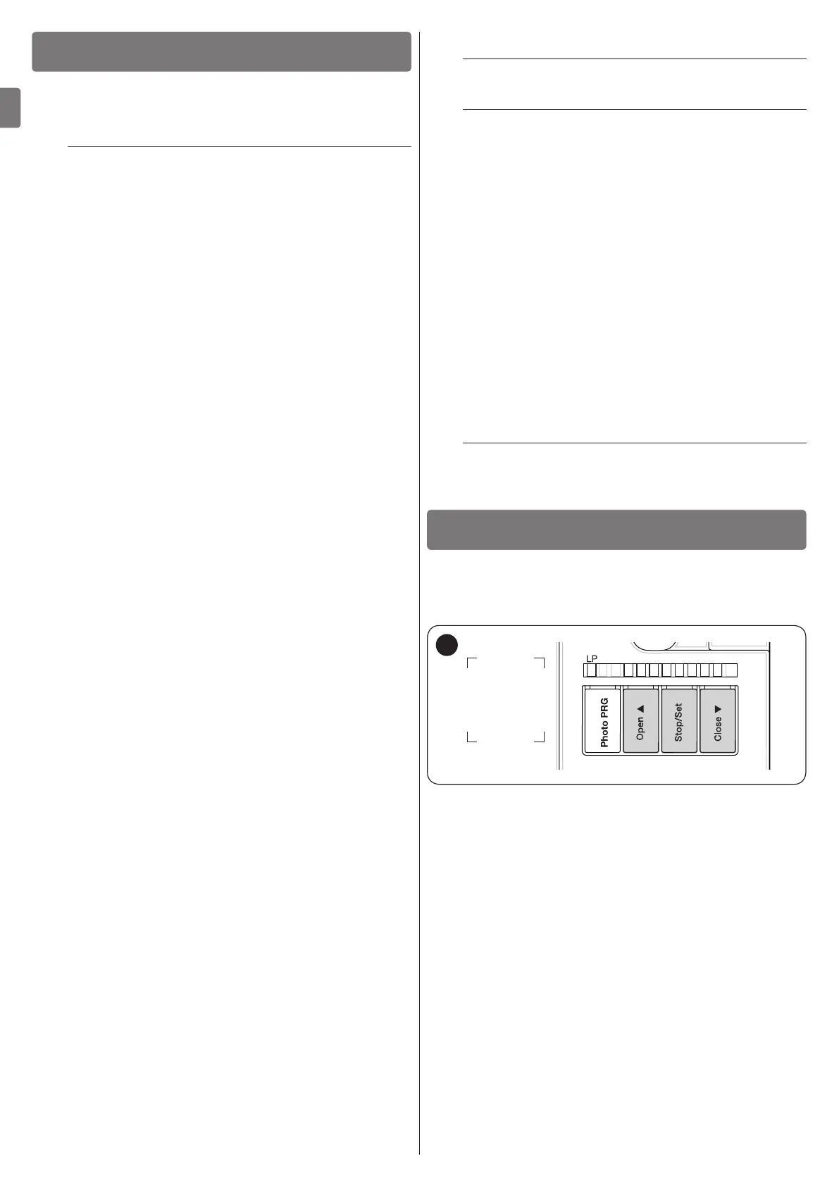
6 PROGRAMMING
There are 3 buttons on the control unit:
f
,
g
and
h
(“Figure 20”) which can be used both for com-
manding the control unit during the testing phase and to pro-
gramme the available functions.
L5 L6 L7 L8L4L3L2L1
20
The available programmable functions are grouped into two
levels and their operating status is signalled by eight LEDs “L1
... L8” located on the control unit (LED lit = function enabled;
LED off = function disabled).
6.1 USING THE PROGRAMMING BUTTONS
f
Button for commanding the gate opening
Selection button during the programming phase.
g
Button used to stop a manoeuvre
If pressed for more than 5 seconds, it allows for entering
the programming mode.
h
Button for commanding the gate’s closure
Selection button during the programming phase.

 Loading...


