QUICK GUIDE: Do not install the unit before you have read all the instructions!
Before you actually start installing the unit check the sturdiness and mechanical consistency of the wing and the observance of
safety margins and minimum distances. Evaluate with particular care the safety devices to be installed and always install an
emergency stop device, in other words, a category 0 stop device.
Once you have carefully analysed the risks involved, you can install the unit, the actuators, the control (key selector or push button
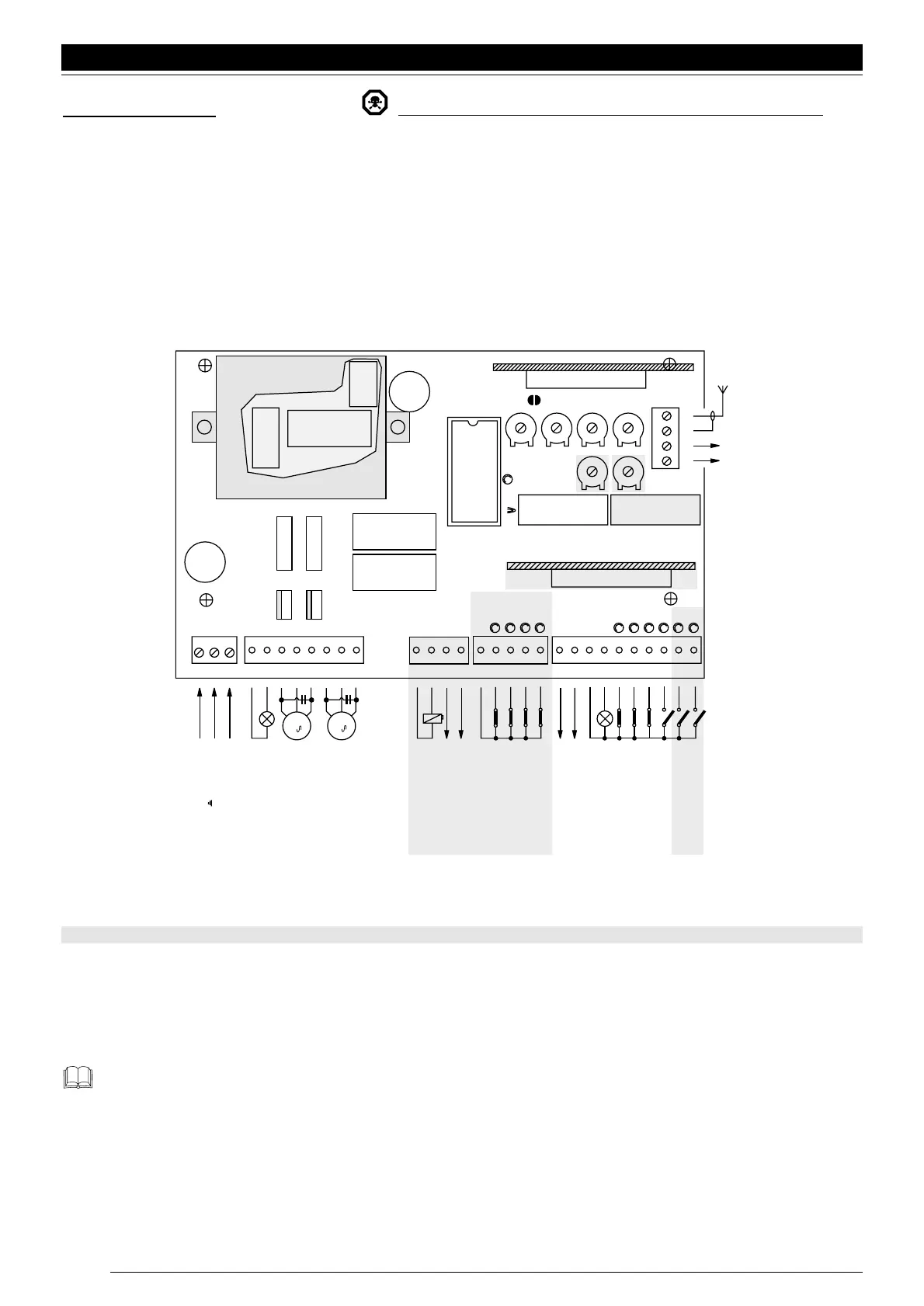
panel) and safety (emergency stop, photoelectric cells, sensitive edges and flashing light) devices; after which connect electrically
following this diagram:
Fig. 1
The highlighted parts are different on the A6, A6F and A700 F versions.
If the inputs of the NC (Normally Closed) contacts are not used they should be jumpered; if there is more than one then they should
be placed in SERIES with one another; if the inputs of the NO (Normally Open) contacts are not used they should be left free and
if there is more than one then they should be placed in PARALLEL with one another. The contacts must be of the mechanical type
and free from any potential; no connections are allowed like those defined as “PNP”, “NPN”, “Open Collector” etc., etc.
Remember that there are specific standards that must be complied with both as regards the safety of the electrical
systems and as regards automatic gates
Release the gearmotors by means of the spanner and check that the gate can move without any difficulty to the end of its travel.
Turn all the function dip-switches round to the “OFF” position so functioning is manual, that is with the button pressed.
Power the unit and check there is a voltage of 230 V a.c. between terminals 1-2 and 1-3 and that there is 24 V a.c. on terminals
21-22; the LEDs on the NC contact inputs must turn on and the OK LED should flash at 1 second intervals.
English
20
 Loading...


