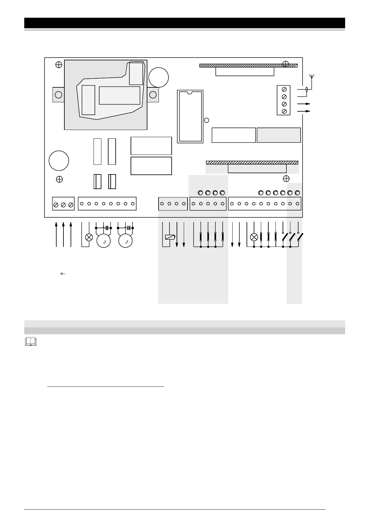
Fig. 4
The highlighted part is only found on the A700F version.
The highlighted part is found on the A6F and A700F versions.
Only qualified, expert personnel may carry out installation and subsequent maintenance, in compliance with the DPR N°
46 dated 5/3/1990, in total observance of the UNI 8612 standards and following the best indications dictated by “expert
workmanship”. Whoever carries out these jobs is held responsible for any damage caused.
2.3) DESCRIPTION OF THE CONNECTIONS:
Here is a brief description of the possible connections of the unit to the outside:
1...3 : 230 Vac = 230 V a.c. 50 Hz
4-5 : Flashing light = Output for connection to the 230 V a.c. flashing light, maximum lamp power 100 W
6...8 : Motor 1 = 230 V a.c. output for connection to the 1st motor, maximum motor power
1
/2 Hp
9...11 : Motor 2 = 230 V a.c. output for connection to the 2nd motor, maximum motor power
1
/2 Hp
Note: Motors 1 and 2 only differ in the start delay; the 1st motor is connected to the opening delay time “TRA” while the
2nd motor is connected to the closing delay time “TRC”. If the delays are unnecessary there is no difference between the motors.
English
25
CH
AP
P. P
FOTO 1
FOTO
ALT
FCA 2
FCC 2
FCA 1
FCC 1
FUSE
44
43
42
41
ANT.
RADIO
FUNCTIONS 1-10 FUNCTIONS 11-20
2° Ch
500mA
FUSE
M1
2
2
M2
5 AF
1 2 3 4 5 6 7 8 9 10 11 12 13 14 15 16 17 18 19 20 21 22 23 24 25 26 27 28 29 30
RADIO
PIU'
CLOSE
OPEN
STEP-BY-STEP
PHOTOCELL 1
PHOTOCELL
STOP
GATE OPEN INDICATOR
COMMON
24 Vac
Max 200 mA
LIMIT SWITCH OPEN 2
LIMIT SWITCH CLOSE 2
LIMIT SWITCH OPEN 1
LIMIT SWITCH CLOSE 1
COMMON
PHOTOTEST (
TX PHOTOCELL
)
24Vac, Max 100 mA
ELECTRIC LOCK
MOTOR 2 CLOSE
MOTOR 2 COMMON
MOTOR 2 OPEN
MOTOR 1 CLOSE
MOTOR 1 COMMON
MOTOR 1 OPEN
LUCY 230 Vac
Max 100 W
LINE 230 Vac "N"
EARTH
LINE 230 Vac "L"
12 Vac, MAX 25 W
 Loading...


